
Annular space type centrifugal extractor and interface radius control method thereof

A centrifugal extractor and annulus-type technology, which is applied in separation methods, solvent extraction, chemical instruments and methods, etc., and can solve problems such as difficulty in adjusting the interface radius of annulus-type centrifugal extraction

Inactive Publication Date: 2017-01-11
ZHENGZHOU TIANYI EXTRACTION TECH
View PDF5 Cites 2 Cited by
  • Summary
  • Abstract
  • Description
  • Claims
  • Application Information

AI Technical Summary

Problems solved by technology

[0006] In view of the above situation, in order to overcome the defects of the prior art, the purpose of the present invention is to provide a ring-gap centrifugal extraction machine, the purpose is to solve the difficulty of adjusting the radius of the ring-gap centrifugal extraction interface without using the air weir pressure to adjust The problem

Method used


Image

  • Annular space type centrifugal extractor and interface radius control method thereof
  • Annular space type centrifugal extractor and interface radius control method thereof
  • Annular space type centrifugal extractor and interface radius control method thereof

Examples


Embodiment Construction

[0021] The specific embodiments of the present invention will be described in further detail below in conjunction with the accompanying drawings.

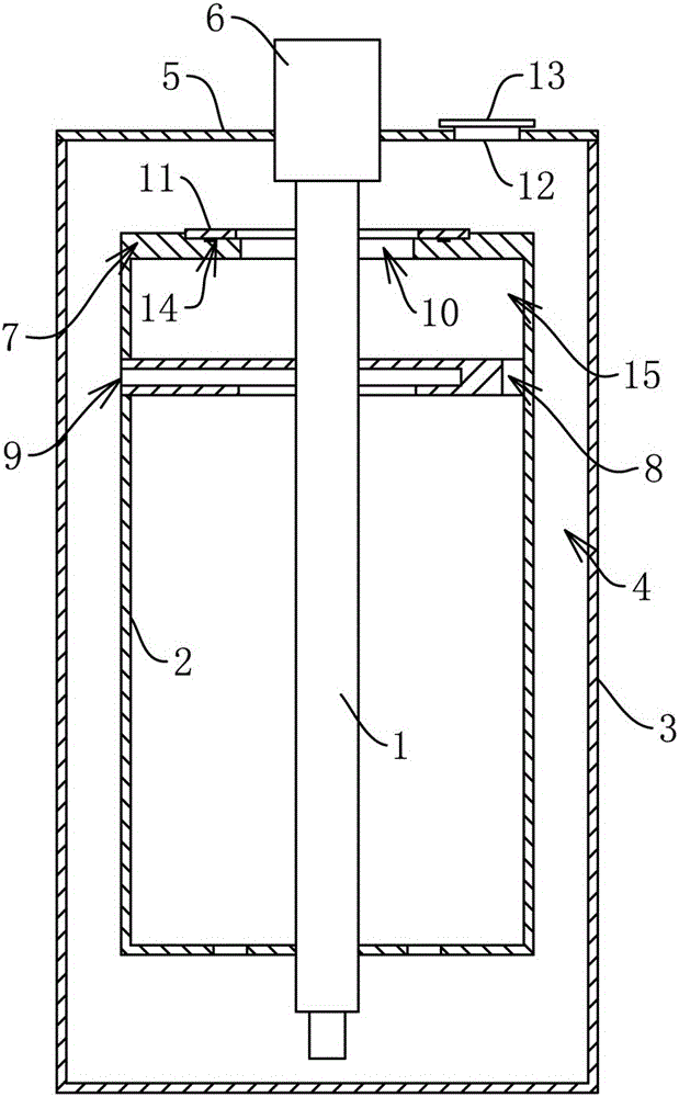
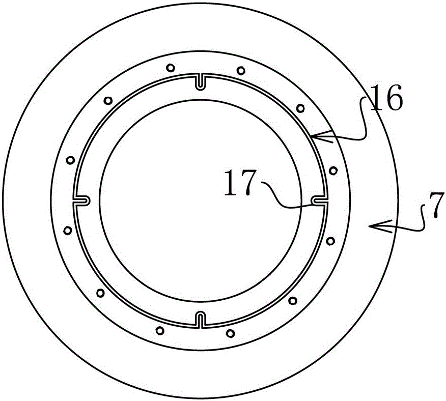
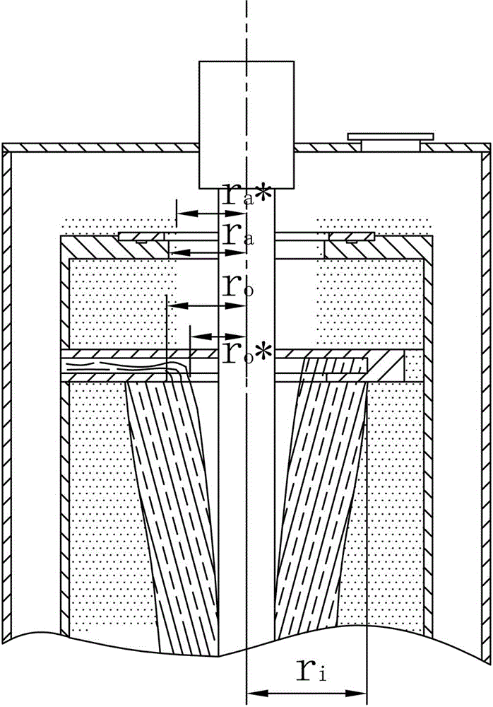
[0022] Examples of annulus centrifugal extractors: such as figure 1 with figure 2 As shown, it includes a rotating shaft 1, a rotating drum 2 and a cylindrical shell 3. The shell 3 is sleeved with the rotating drum 2 and an annular gap 4 is provided between the shell 3 and the rotating drum 2. The shell 3 is provided with heavy and light phase inlets, and the shell 3 The bottom is closed and the upper end is provided with a cover plate 5. The rotating drum 2 and the rotating shaft 1 are in rotation-stop fit. The upper end of the rotating shaft 1 is connected with a motor 6 fixedly connected with the cover plate 5, forming the motor 6 to drive the rotating drum 2 through the rotating shaft 1 to rotate at a high speed The bottom of the drum 2 is provided with a bottom plate and the bottom plate is provided with an inlet communicating wi...


PUM


Abstract

The invention provides an annular space type centrifugal extractor. The problem that adjustment is difficult on the condition that an annular space type centrifugal extraction interface radius is not adjusted by adopting air weir pressure is solved. The annular space type centrifugal extractor comprises a rotating shaft, a rotating drum and a cylinder type shell. The rotating drum is sleeved with the shell, and an annular space is formed between the rotating drum and the shell. The shell is provided with heavy and light phase inlets. The bottom of the shell is closed, and a cover plate is arranged at the upper end of the shell. The rotating drum and the rotating shaft are in check fit. A motor is connected to the upper end of the rotating shaft in a transmission mode. The motor is fixedly connected with the cover plate. The bottom of the rotating drum is provided with a base plate. The base plate is provided with an inlet communicated with the interior of the rotating drum. A split weir body is arranged at the upper end of the rotating drum. A discharging outlet is formed in the position, corresponding to the split weir body, of the rotating shaft. An annular heavy phase weir plate is detachably fixed and connected to the upper end face of the discharging outlet in a sealed mode. The heavy phase weir plate is formed by splicing a plurality of arc sections. All components of the heavy phase weir plate are allowed to be taken out from an adjusting opening, the adjusting opening is covered with a sealing cover in a sealed mode, and the interface radius can be adjusted on the condition that adjustment is performed by adopting no air weir pressure.

Description

Technical field [0001] The invention relates to the field of centrifugal extraction, in particular to an annulus type centrifugal extractor, and provides a method for controlling the interface radius of the extractor. Background technique [0002] The working process of the centrifugal extractor is mainly divided into two parts: the mixing mass transfer process and the centrifugal separation process. The two immiscible liquids to be mixed are mixed under the rotating action of the rotating drum or paddle of the centrifugal extractor to complete the mixing. The latter mixed liquid enters the drum and rotates at a high speed under the drive of the drum to generate centrifugal force. Under the action of centrifugal force, the dense liquid gathers outwards, and the low-density liquid gathers inwards, and the two liquids will gradually layer and form. At one interface, the denser liquid on the outer side is discharged from the extractor through the heavy phase outlet, and the liquid w...

Claims


Application Information

Patent Timeline
IPC IPC(8): B01D11/04
CPCB01D11/048B01D11/0484
Inventor 王利军
Owner ZHENGZHOU TIANYI EXTRACTION TECH
Learn More