
A catalytic device for preparing u(iv) solution

A catalytic device and solution technology, which is applied in the field of catalytic reaction equipment for preparing U solution, can solve problems such as hidden safety hazards and complex structures, and achieve the effects of improved safety, less wear and tear, and mild reaction conditions

Active Publication Date: 2020-05-19
CHINA INSTITUTE OF ATOMIC ENERGY
View PDF7 Cites 0 Cited by
  • Summary
  • Abstract
  • Description
  • Claims
  • Application Information

AI Technical Summary

Problems solved by technology

But the above-mentioned hydrogenation catalytic reduction equipment for preparing U(IV) solution is a high-pressure equipment, and the use of high-pressure hydrogen as a reductant is a great safety hazard in the environment of radioactive extremely strong nuclear fuel reprocessing; in addition, in addition to the main reaction equipment , in order to realize the separation of product liquid and the recycling of gas, it also needs supporting equipment such as high-pressure separator and low-pressure separator, and the structure is relatively complicated

Method used


Image

  • A catalytic device for preparing u(iv) solution
  • A catalytic device for preparing u(iv) solution
  • A catalytic device for preparing u(iv) solution

Examples


Embodiment 1

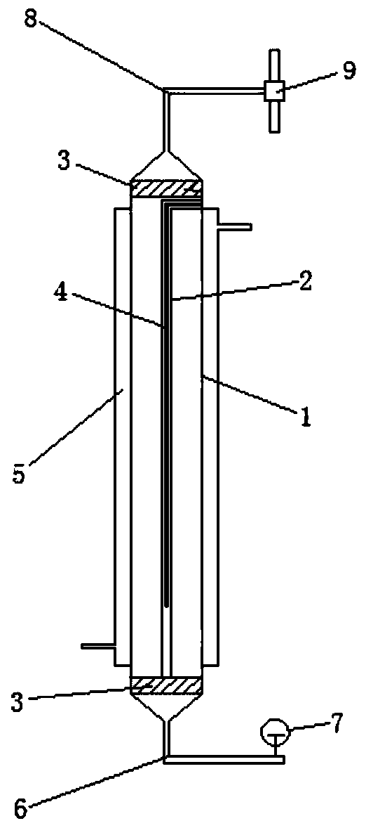
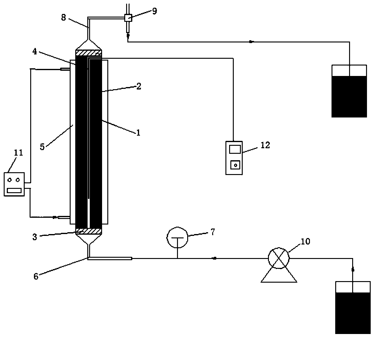
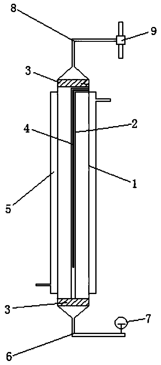
[0024] The annular zone between the inner tube 2 and the outer tube 1 is the reaction zone, filled with Pt / SiO 2 For the catalyst, the loading amount of Pt is 1%; the filling height of the catalyst is 600 mm. Pt / SiO 2 The catalyst is prepared by impregnation method.

[0025] The process of adopting the present invention to prepare U(IV) is as follows: first inject the prepared raw material liquid from the bottom feed port 6 of the catalytic reaction device by the feed pump 10, and the composition of the raw material liquid is: 203g / L UO 2 (NO 3 ) 2 -0.80mol / LHNO 3 -1.0mol / LN 2 h 5 NO 3 After the holes of the sintered stainless steel plate 3 make the feed liquid evenly distributed, enter the annular reaction zone, react with the catalyst, control the reaction temperature by circulating water bath, obtain U(IV) solution and gas product, and the product is discharged from the outlet of the reaction column 6 flows out, realizes the separation of U(IV) solution and gas thro...

Embodiment 2

[0028] The implementation mode of this embodiment is the same as that of Example 1, the difference is that the diameter of the inner tube 3 of the reaction column in this embodiment is 6mm, the diameter of the outer tube 2 is 30mm, the filling height of the catalyst is 300mm, and the Pt / SiO2 filled therebetween 2 The loading of Pt in the catalyst is 3%, and the raw material liquid composition is 201g / L UO 2 (NO 3 ) 2 -0.83mol / LHNO 3 -1.3mol / L N 2 h 5 NO 3 , the temperature of the water bath is 50°C, the concentration of U(IV) at the outlet is 198g / L, and the productive rate of U(IV) can reach 98.5%.


PUM

PropertyMeasurementUnit
heightaaaaaaaaaa

Abstract

The invention discloses a catalytic device for preparing a U(IV) solution. The device comprises an outer pipe, an inner pipe, a jacket, sintered stainless steel plates, a feeding hole and a discharging hole, wherein an annular structure is formed by the inner pipe in the outer pipe; the sintered stainless steel plates are arranged at the upper and lower ends of the outer pipe; the jacket is arranged on the exterior of the outer pipe; the feeding hole is formed in the bottom of the sintered stainless steel plate at the lower end; the discharging hole is formed in the top of the sintered stainless steel plate at the upper end. The catalytic device for preparing the U(IV) solution provided by the invention has the advantages of simple structure, mild catalytic reaction condition, easily controlled process, safety, reliability, easiness in continuous production and capability of continuously running in long period.

Description

technical field [0001] The invention belongs to the field of nuclear fuel reprocessing, and in particular relates to a catalytic reaction device for preparing U(IV) solution. Background technique [0002] The preparation technology of U(IV) plays an important role in the realization of the Purex process. Regarding the preparation technology of U(IV) solution, direct electrolysis of UO was initially used 2 (NO 3 ) 2 The method of preparing U(IV) in aqueous solution, but the volume of the electrolysis device is large, the production cycle is long, the yield of U(IV) is low, and the operating conditions are relatively high. In practical applications, there are still problems such as electrode deactivation and must be replaced regularly. [0003] Due to the above-mentioned problems in the preparation of U(IV) by the traditional electrolysis method, the technology of preparing U(IV) solution by catalytic hydrogenation was adopted later. Take U.S. Patent US6759027 as an examp...

Claims


Application Information

Patent Timeline
Patent Type & Authority Patents(China)
IPC IPC(8): B01J8/02
CPCB01J8/0257B01J8/0285B01J2208/00044B01J2208/00212B01J2208/00407
Inventor 李斌何辉叶国安张秋月宋鹏黄小红陈延鑫兰天李会蓉唐洪彬
Owner CHINA INSTITUTE OF ATOMIC ENERGY
Learn More