Positioning system and method for punching of bolt holes in root portion of wind turbine blade

A technology of wind power blades and positioning system, applied in metal processing and other directions, can solve problems such as unfavorable blade weight control, take up a lot of time, reduce blade production efficiency, etc. The effect of process stability

Active Publication Date: 2017-01-11
LUOYANG SUNRUI WIND TURBINE BLADE
View PDF3 Cites 5 Cited by
  • Summary
  • Abstract
  • Description
  • Claims
  • Application Information

AI Technical Summary

Problems solved by technology

A trial drilling includes trial drilling bolt hole marks, measuring the distance from the center of each bolt hole to the inner and outer walls of the blade shell, and milling the bolt hole marks; usually, if a wall thickness does not meet the requirements, it is necessary to adjust the position of the blade root bracket or blade, Perform a trial drilling again; in addition, in order to avoid the blade length being smaller than the theoretical value caused by the blade trial drilling cutting and milling the blade end face, usually a large length margin is left when the blade is cut, so the wind power blade is formally drilled The previous trial drilling step will take up a lot of time, which reduces the production efficiency of the blade and is not conducive to the control of the weight of the blade

Method used


Image

  • Positioning system and method for punching of bolt holes in root portion of wind turbine blade
  • Positioning system and method for punching of bolt holes in root portion of wind turbine blade
  • Positioning system and method for punching of bolt holes in root portion of wind turbine blade

Examples


Embodiment Construction

[0022] Below in conjunction with accompanying drawing and specific embodiment the present invention is described in further detail:

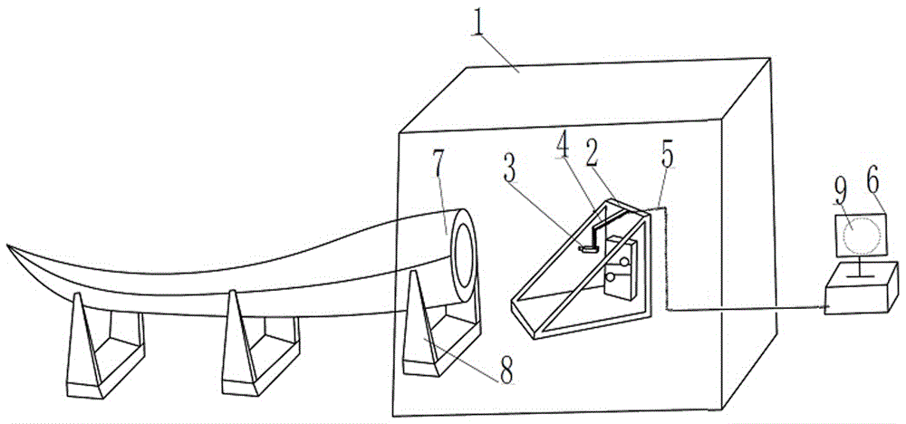
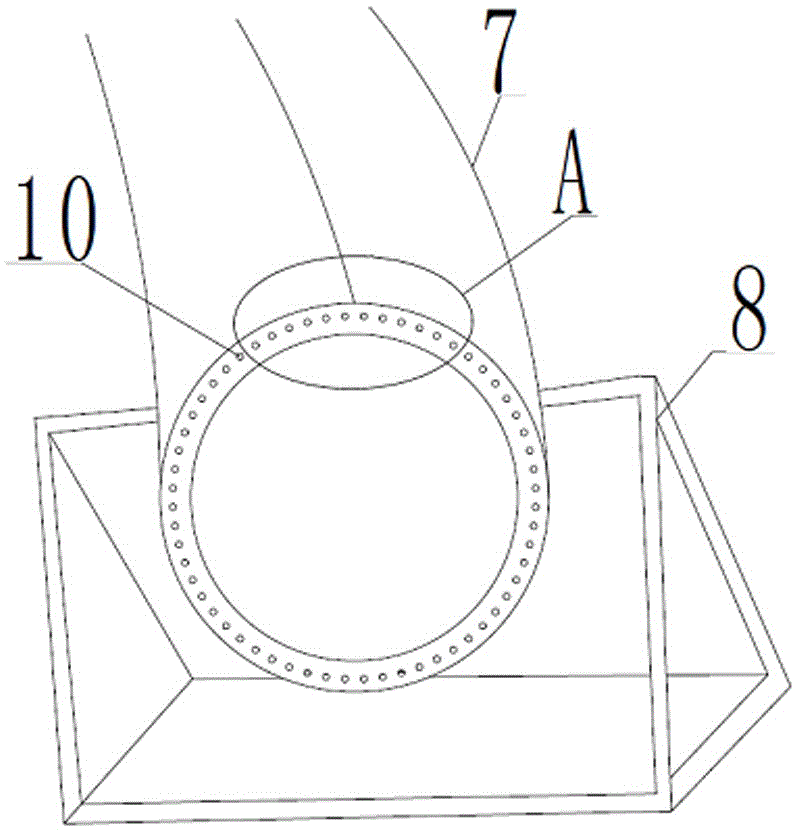
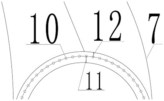
[0023] As shown in the figure: a positioning system for punching bolt holes at the root of wind power blades, including a computer 6, an imaging room 1, a root adjustment bracket 8, an optical imager 3, an imager bracket 4 and a punching hole set in the imaging room 1 The equipment bracket 2, the surroundings of the imaging chamber 1 are made up of opaque partitions, one of which is provided with a through hole for the root of the wind power blade 7 and the root adjustment bracket 8 to be inserted into the imaging chamber 1, so that the imaging chamber 1 Surrounding the punching equipment and the root of the wind turbine blade 7, the root adjustment bracket 8 is used to adjust the vertical and horizontal positions of the root of the wind turbine blade 7;

[0024] The optical imager 3 is fixedly arranged on one end of the imager support 4, and th...


PUM


Abstract

The invention provides a positioning system for punching of bolt holes in the root portion of a wind turbine blade. The positioning system comprises a computer, an imaging room, a root portion adjustment support, an optical imaging instrument, an imaging instrument support and a punching equipment support. A through hole is formed in one wall of the imaging room. The root portion adjustment support is used for adjusting the vertical position and the horizontal position of the root portion of the wind turbine blade. The optical imaging instrument is fixed to one end of the imaging instrument support. The other end of the imaging instrument support is hinged to a cross beam at the top end of the punching equipment support. The optical imaging instrument is electrically connected with the computer and can project a distribution diagram of bolt holes in the root portion of a standard blade onto the end face of the root portion of the wind turbine blade according to the proportion of 1:1. According to the positioning system for punching of the bolt holes in the root portion of the wind turbine blade, an accurate and convenient positioning mode for punching is achieved in the way that the imaging instrument is used for projection, complex punching trial operation before punching of a wind turbine blade in the prior art is avoided, the production efficiency of the blade is improved, and the bolt hole punching process for the blade can be monitored in real time.

Description

technical field [0001] The invention relates to the technical field of auxiliary equipment for processing wind power blades, in particular to a positioning system for drilling bolt holes at the root of wind power blades and a positioning method thereof. Background technique [0002] Glass fiber wind turbine blades are one of the key components of wind turbines, and wind turbine blades are mostly connected to wind turbines by "T-bolt connection". The design of this root connection method requires cutting, milling, and drilling of nut holes and bolt holes at the blade root with drilling equipment after the blades are bonded and formed. In order to ensure the connection strength of the blade root, not only all bolt holes are required to be evenly distributed on the pitch circle of a certain diameter on the blade root end surface, but also the thickness from the edge of the bolt hole to the inner wall and outer wall of the blade root should also meet a certain numerical requirem...

Claims


Application Information

Patent Timeline
Patent Type & Authority Applications(China)
IPC IPC(8): B26D7/01B26F1/16
CPCB26D7/01B26F1/16
Inventor 谢惠冯威赵金国宋震洋
Owner LUOYANG SUNRUI WIND TURBINE BLADE
Why Eureka
Try Eureka