A UAV ejection and sliding device and ejection system
An unmanned aerial vehicle (UAV) and sliding technology, which is applied in the direction of launch/drag transmission device, etc., can solve the problems of damage to the catapult structure, poor connection method, damage to the UAV structure, etc., to avoid direct contact, durable use, and use. stable effect
- Summary
- Abstract
- Description
- Claims
- Application Information
AI Technical Summary
Problems solved by technology
Method used
Image
Examples
Embodiment 1
[0037] The unmanned aerial vehicle ejection and sliding device provided in this embodiment is arranged on the ejection rack and is used to carry the unmanned aerial vehicle and eject the unmanned aerial vehicle. It includes a locking mechanism and a sliding track set on the ejection rack. A sliding frame for carrying drones and a pulley arranged at the bottom end of the sliding frame, and the locking mechanism is arranged at one end of the sliding frame close to the initial end of the ejection frame, and is used to remove the The man-machine is locked at the initial end of the ejection frame.
[0038] In the prior art, since the UAV is in direct contact with the ejection frame, the contact position is the bearing point of the UAV itself or the redundant structure extended by the UAV serves as the force point of the ejection, which causes certain impact on the structure and life of the aircraft. It is easy to cause the loss of the structure of the UAV and the structure of the ejec...
Embodiment 2
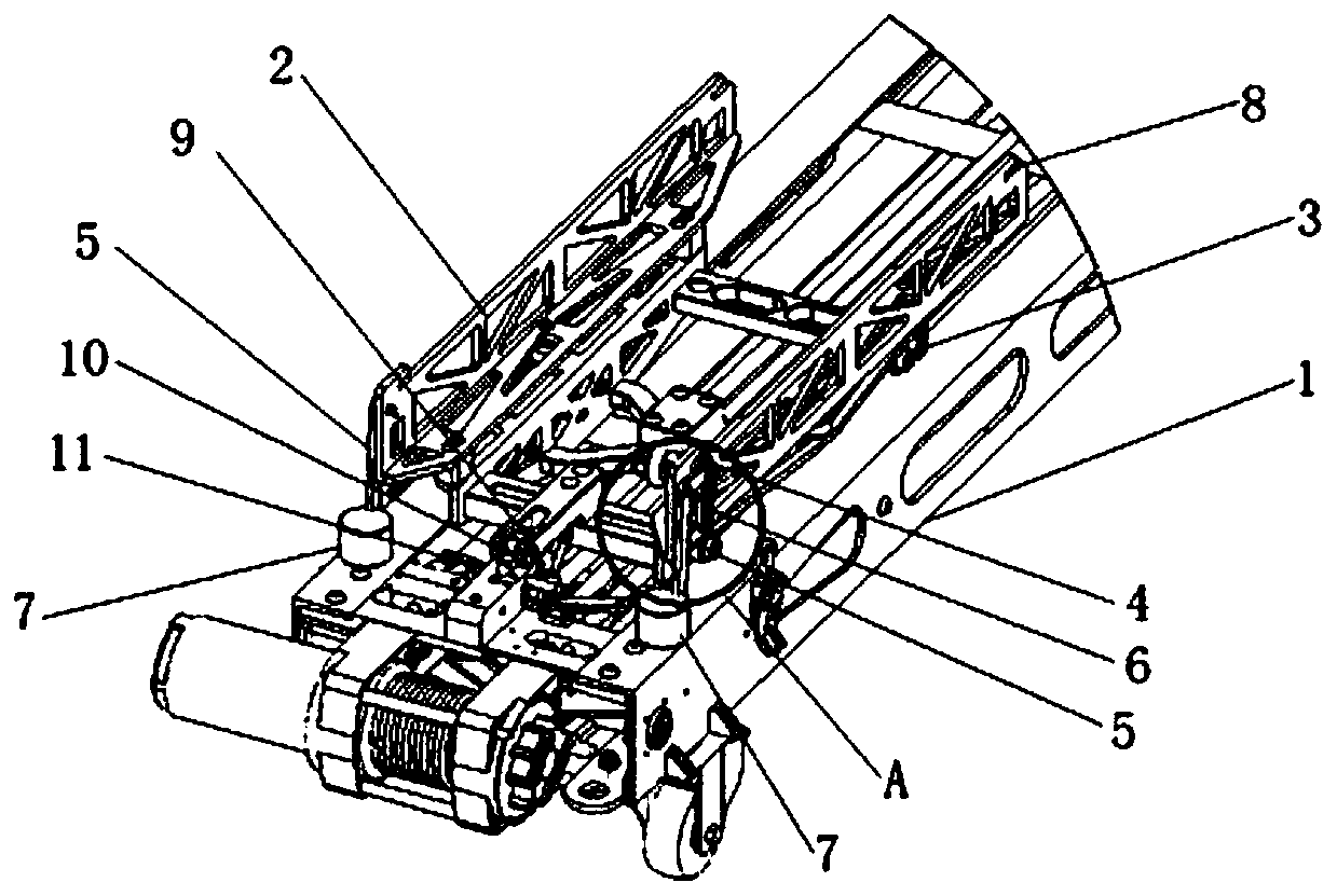
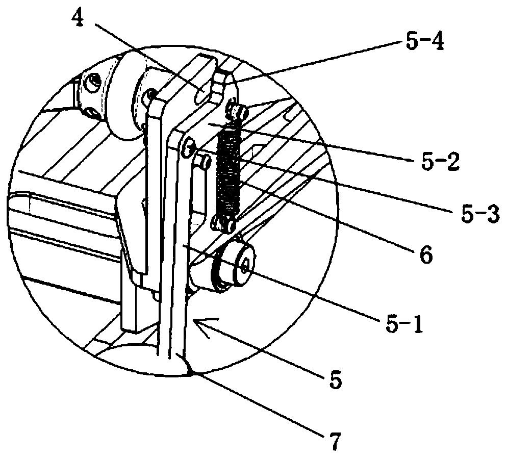
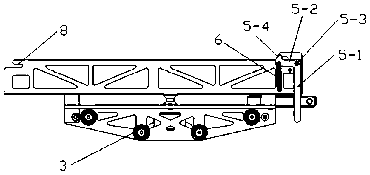
[0040] Such as Figure 1 to 3 As shown, the unmanned aerial vehicle ejection and sliding device provided by this embodiment is arranged on the ejection frame 1 for carrying the unmanned aerial vehicle and ejecting the unmanned aerial vehicle. It includes a locking mechanism and is arranged on the ejection frame 1. The sliding frame 2 used to carry the drone on the sliding track and the pulley 3 arranged at the bottom end of the sliding frame 2, the locking mechanism is arranged on the sliding frame 2 close to the ejection frame 1 One end of the initial end is used to lock the drone on the initial end of the ejection frame 1.
[0041] The locking mechanism includes a first slot 4 and a first limiting member. The opening direction of the first slot 4 is consistent with the moving direction of the sliding frame 2 and is used to accommodate the drone. The first fixing part at the bottom; when the sliding frame 2 is at the initial end of the ejection frame 1, the first limiting member...
Embodiment 3
[0048] Such as Figure 4 to 7 As shown, this embodiment provides an unmanned aerial vehicle ejection system, which includes a driving mechanism, an ejection frame, and the unmanned aerial vehicle ejection and sliding device according to the first embodiment or the second embodiment arranged on the ejection frame 12. The wire rope 15, the rubber band, the connecting rope, the anti-collision rope 13, the first metal plate and the second metal plate; one end of the wire rope 15 is connected to the drive mechanism 14 provided at the initial end of the ejection frame, and the other end is connected to The first metal plate is connected, and the first metal plate is slidably connected to the ejection frame 1, and is located between the running frame 2 and the end of the ejection frame 1; the second metal plate is connected to the ejection frame 1; The ejection frame 1 is slidably connected, and is located between the first metal plate and the end of the ejection frame 1, the rubber b...
PUM
 Abstract
Description
Claims
Application Information
 - R&D
- Intellectual Property
- Life Sciences
- Materials
- Tech Scout
- Unparalleled Data Quality
- Higher Quality Content
- 60% Fewer Hallucinations
Browse by: Latest US Patents, China's latest patents, Technical Efficacy Thesaurus, Application Domain, Technology Topic, Popular Technical Reports.
© 2025 PatSnap. All rights reserved.Legal|Privacy policy|Modern Slavery Act Transparency Statement|Sitemap|About US| Contact US: help@patsnap.com


