
Airing mechanism

A technology for drying clothes and clothes rails, which is applied to washing devices, textiles and papermaking, household appliances, etc., and can solve the problems of occupying a large space, large volume, and occupying a large space, so as to overcome the lack of indoor space and the inability to overcome The effect of moving and improving the efficiency of use

Active Publication Date: 2017-01-11
SHANGHAI DIANJI UNIV
View PDF2 Cites 0 Cited by
  • Summary
  • Abstract
  • Description
  • Claims
  • Application Information

AI Technical Summary

Problems solved by technology

[0002] Most of the drying racks on the market at this stage are mostly fixed in one place and require a dedicated space to use the drying racks, which cannot meet the needs of users in different situations, and need to purchase special clothes racks for supporting use. Although some drying racks can be moved and used in different positions, once they are used, they will take up a lot of space. They are immovable, not easy to carry and large in size, and they are not windproof. They cannot be used in small apartments and school dormitories. Most of them are floor type or lift type. Although they can be used in small apartments and school dormitories, they will occupy a large space and the scope of application is very limited. With the acceleration of urbanization and the increase of floating population, especially In order to save the cost of living, the outsiders live in a small space. If you use a common clothes rack, you not only need to buy a lot, but also occupy a lot of space, which cannot meet the needs of various users. Therefore, it is necessary to design a Too much space, a flexible and convenient clothes drying rack

Method used


Image

  • Airing mechanism
  • Airing mechanism
  • Airing mechanism

Examples


Embodiment Construction

[0020] In order to make the technical means, creative features, goals and effects achieved by the present invention easy to understand, the present invention will be further elaborated below in conjunction with illustrations and specific embodiments.

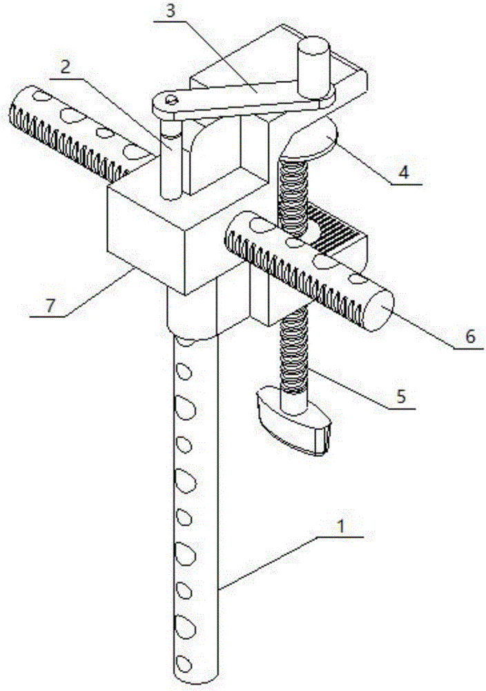
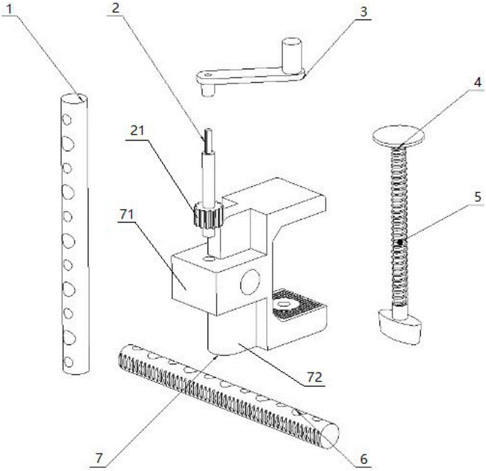
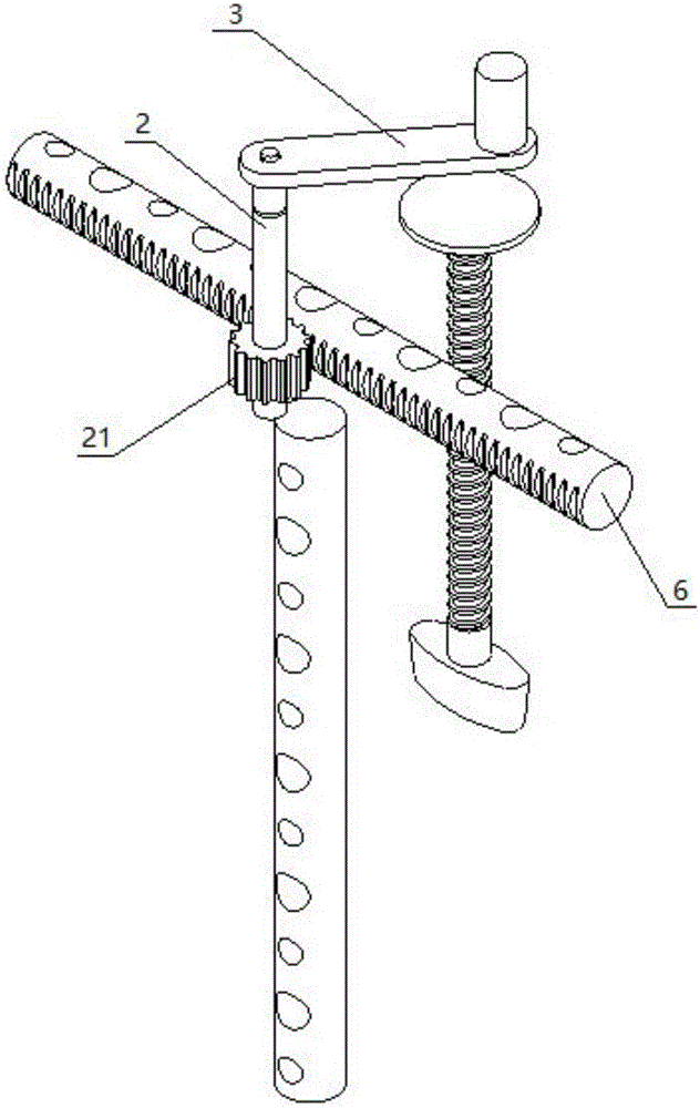
[0021] refer to figure 1 , figure 2 As shown, the clothes-drying mechanism includes a clothes-drying pole and a control mechanism, and the clothes-drying pole and the control mechanism are installed on the main body 7, and the clothes-drying pole includes a longitudinal clothes-drying pole 1 and a horizontal clothes-drying pole 6, and the control The mechanism includes a handle 3, a horizontal clothes rail control mechanism 2 and a screw rod 5 with a handle. One side of the main body 7 is open, and one side of the main body 7 opening is provided with two upper and lower top plates, and the other side of the main body 7 is provided with a convex Block 71, one side of the raised block 71 is provided with a hole, the hole runs th...


PUM


Abstract

An airing mechanism comprises an airing rod and a control mechanism. The airing rod and the control mechanism are installed on a main body. The airing rod comprises a longitudinal airing rod and a transverse airing rod. The control mechanism comprises a handle, a transverse airing rod control mechanism and a threaded rod with a handle. One side of the main body is provided with an opening, one side of the opening of the main body is provided with an upper top plate and a lower top plate, the other side of the main body is provided with a protruded block, and one side of the protruded block is provided with a hole. The airing mechanism is composed of a steel pipe, clamps and screws and the like and is firm, less in used material and simple to operate, the shortcoming that a conventional hanger is not movable and cannot be carried is overcome, and the airing mechanism is simply combined with hands to be used, is not subjected to influences of objective conditions and can be used for indoor and outdoor airing. After use, the airing mechanism can be placed only after simple dismantling, and the shortcoming of insufficient indoor space can be effectively overcome. The airing rod is provided with holes of different sizes, various hangers can be aired conveniently, various clothes supports can be matched to be used, and the use efficiency is improved.

Description

technical field [0001] The invention relates to the field of daily necessities, in particular to a clothes drying mechanism. Background technique [0002] Most of the drying racks on the market at this stage are mostly fixed in one place and require a dedicated space to use the drying racks, which cannot meet the needs of users in different situations, and need to purchase special clothes racks for supporting use. Although some drying racks can be moved and used in different positions, once they are used, they will take up a lot of space. They are immovable, not easy to carry and large in size, and they are not windproof. They cannot be used in small apartments and school dormitories. Most of them are floor type or lift type. Although they can be used in small apartments and school dormitories, they will occupy a large space and the scope of application is very limited. With the acceleration of urbanization and the increase of floating population, especially In order to sav...

Claims


Application Information

Patent Timeline
Patent Type & Authority Applications(China)
IPC IPC(8): D06F57/12
CPCD06F57/12
Inventor 杜浩明郭小艳
Owner SHANGHAI DIANJI UNIV
Learn More