
Vacuum suction cup

A vacuum suction cup, vacuum suction technology, applied in suction cups, connecting components, mechanical equipment, etc., can solve the problems of limited number of suction cups, vacuum loss, workpiece scratches, etc., to increase the scope of use, increase vacuum suction, improve The effect of stability

Active Publication Date: 2018-06-22
NOHAN TECH
View PDF5 Cites 0 Cited by
  • Summary
  • Abstract
  • Description
  • Claims
  • Application Information

AI Technical Summary

Problems solved by technology

[0003] In the case of contact vacuum chucks, the principle is to directly apply negative pressure at the air inlet of the suction cup, and generate suction at the air outlet of the suction cup to achieve the effect of adsorbing the workpiece, but the suction surface of the suction cup must be covered within the solid range, otherwise it will cause Vacuum loss cannot pick up the workpiece
[0004] Furthermore, the fixing method of the suction cup is generally based on the size of the suction surface of the suction cup to make a fixed frame. The number of the suction cups is limited and cannot be adjusted automatically at random. It must be manually adjusted, which will increase the inconvenience of operation.
[0005] For non-contact suction cups, there is still a small distance between the adsorption surface and the surface of the workpiece when it absorbs the workpiece, so the workpiece cannot be sucked tightly. When the suction cup moves or rotates at high speed, the inertial force generated by the acceleration will throw the workpiece away. In addition, the adsorption surface of the non-contact suction cup is generally made of hard materials, such as engineering plastics or aluminum alloy, and because there is a certain distance between it and the adsorption workpiece, it is impossible to set a softer cushion in order to enhance the suction force. When the adsorption surface is in contact with the workpiece, it is easy to cause scratches on the workpiece
[0006] The above two existing vacuum chucks still have deficiencies that need to be improved, so how to solve the above problems and make the contact vacuum chucks more widely used is the goal that the inventors and those engaged in this industry want to improve.

Method used


Image

  • Vacuum suction cup
  • Vacuum suction cup
  • Vacuum suction cup

Examples


Embodiment Construction

[0034] In order to achieve the above-mentioned purpose and effect, the technical means and the structure thereof adopted in the present invention are hereby illustrated in detail with respect to the preferred embodiments of the present invention. Its features and functions are as follows, so as to fully understand.

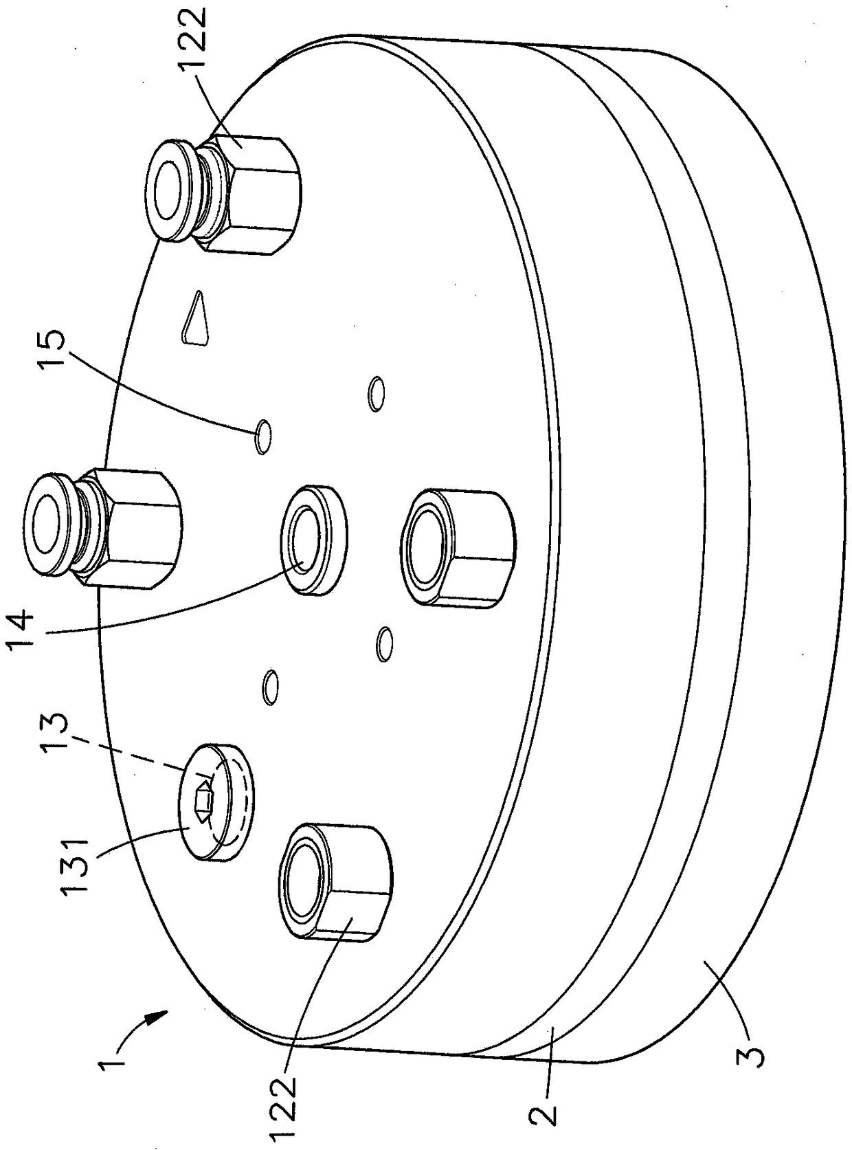
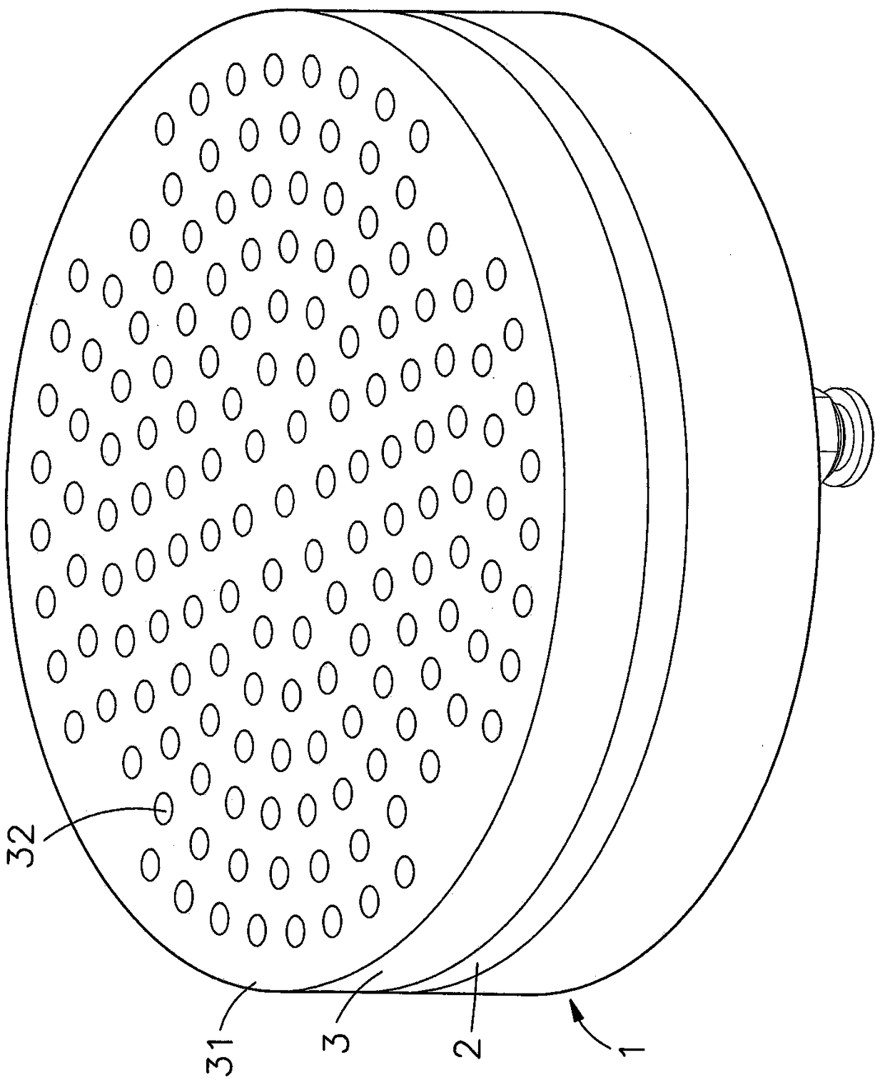
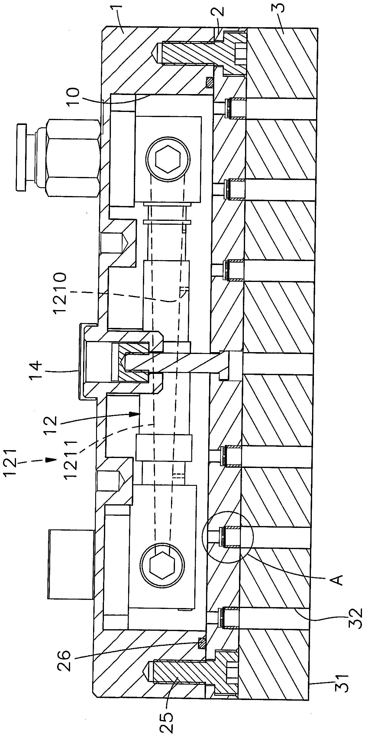
[0035] see figure 1 , figure 2 , image 3 , Figure 4 , Figure 7 As shown, it can be clearly seen from the figure that it includes a seat body 1, a base 2 and a contact cushion 3, wherein:

[0036] The bottom of the seat body 1 is recessed with an air groove 10, the top surface of the seat body 1 is provided with a plurality of through grooves 11 connected to the air groove 10, and a vacuum suction device 12 is installed at the plurality of through grooves 11, and the top surface of the seat body 1 There is also a cleaning notch 13 connected to the air tank 10, and a cleaning screw 131 is locked on the cleaning notch 13. The center of the top surface of the ...


PUM


Abstract

The invention relates to a vacuum sucker. The vacuum sucker comprises a base body, a base under the base body, and a contact soft pad under the base, wherein an air groove at the bottom of the base body is provided with vacuum attraction devices in multiple through grooves; multiple intake channels are recessed in the bottom surface of the base; pressing valve pieces are arranged in the intake channels; through holes are formed in the centers of the pressing valve pieces; the vacuum sucker is displaced up and down by dint of the pressing valve pieces during using; and as the through holes are only used for communicating to reduce the area to increase the vacuum suction and to reduce the vacuum loss when not absorbing a preset object, the vacuum sucker can be stably attracted without throwing during high-speed moving, and widens the application range.

Description

technical field [0001] The invention relates to a vacuum suction cup, especially a suction cup that uses vacuum to attract preset objects. The air inlet channel of the base under the seat is provided with a pressure valve plate that moves back and forth, and the area is reduced by means of the central perforation of the pressure valve plate. In order to increase the vacuum suction and reduce the vacuum loss due to failure to absorb the preset object. Background technique [0002] According to, vacuum chucks are used more and more frequently in the processing or transportation of today's industries. The technology of vacuum chucks can be mainly divided into two types, one is contact vacuum chucks, and the other is non-contact vacuum chucks. Generally speaking , the more common and widely used is the contact vacuum chuck technology. [0003] In the case of contact vacuum chucks, the principle is to directly apply negative pressure at the air inlet of the suction cup, and gene...

Claims


Application Information

Patent Timeline
Patent Type & Authority Patents(China)
IPC IPC(8): F16B47/00
Inventor 张琼君
Owner NOHAN TECH
Learn More