
Horizontally mounted compressor

A compressor, horizontal type technology, applied in the direction of mechanical equipment, machines/engines, liquid fuel engines, etc., can solve problems such as difficult to increase the side pressure of electric components, and achieve the effect of improving reliability

Inactive Publication Date: 2014-07-09
SANYO ELECTRIC CO LTD
View PDF8 Cites 1 Cited by
  • Summary
  • Abstract
  • Description
  • Claims
  • Application Information

AI Technical Summary

Problems solved by technology

[0008] In the aforementioned Patent Document 2, a baffle plate is used to divide the inside of the airtight container into the electric element side and the compression mechanism side, and by discharging the refrigerant gas into the airtight container on the electric element side, the pressure on the electric element side is increased, thereby , it is possible to increase the oil level on the side of the compression mechanism of the baffle and reliably suck the oil by the oil pump. However, since the pressure loss is small when carbon dioxide is used as the refrigerant, it is difficult to increase the pressure on the side of the electric element, and the compression The problem that the oil level on the mechanism side hardly rises

Method used


Image

  • Horizontally mounted compressor
  • Horizontally mounted compressor

Examples


Embodiment Construction

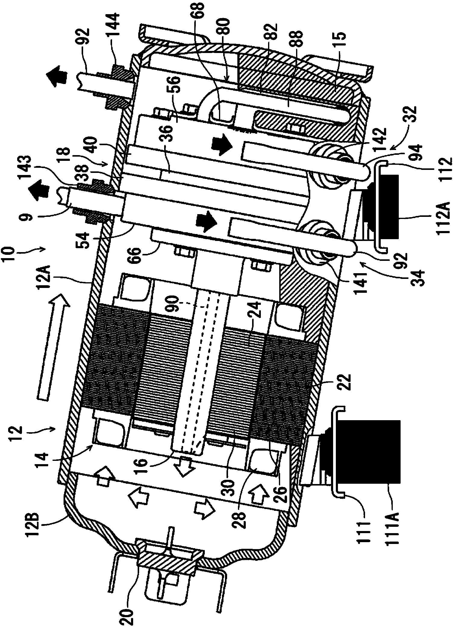
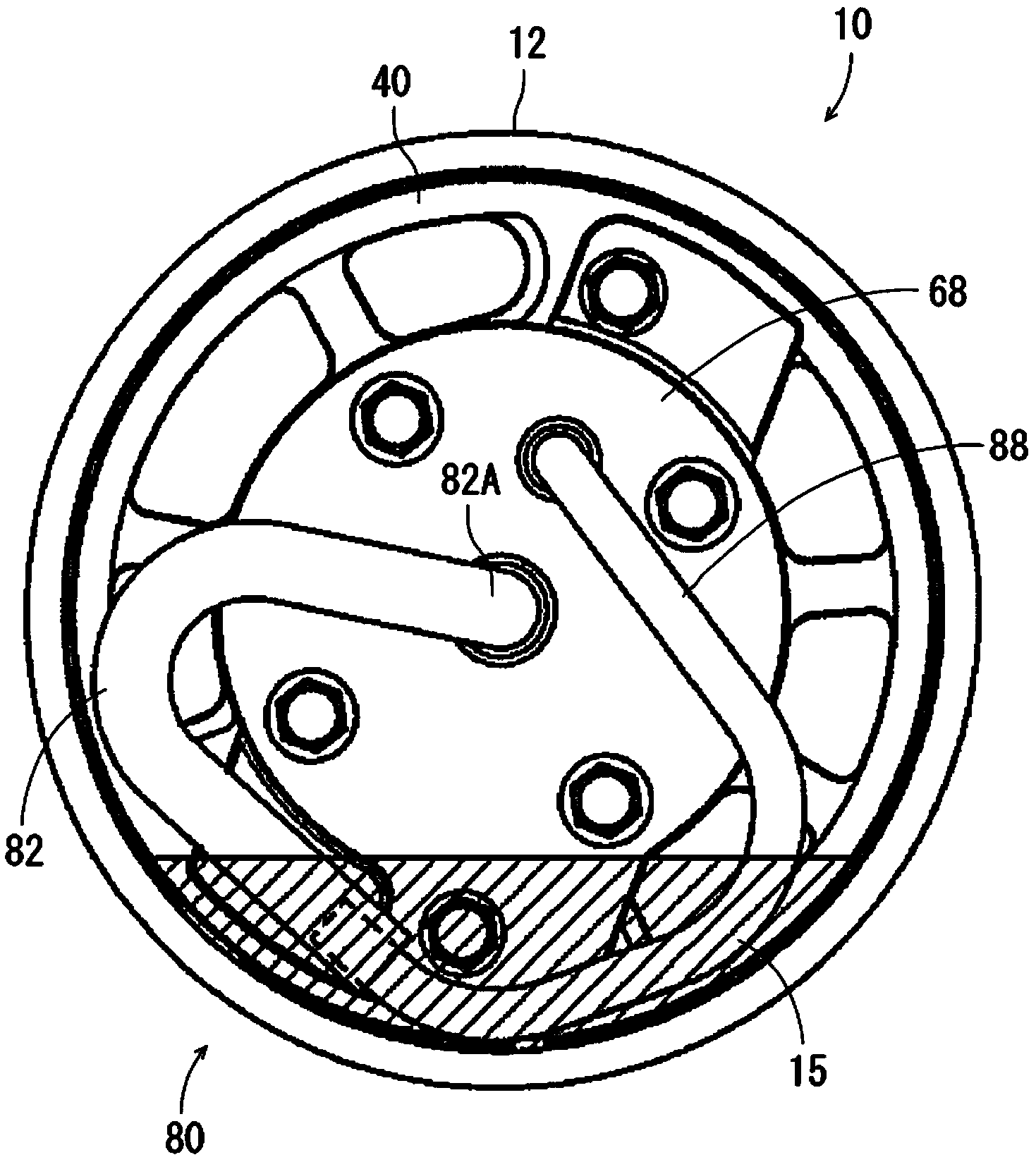
[0036] Hereinafter, embodiments of the present invention will be described in detail. In each figure, 10, as an embodiment of the horizontal type compressor of the present invention, is to convert carbon dioxide (CO 2 ) is used as a horizontal type internal intermediate pressure type multi-stage compression rotary compressor used as a refrigerant. This multi-stage compression rotary compressor (compressor) 10 has a horizontally elongated cylindrical airtight container 12 with both ends sealed, and the inner bottom of the airtight container 12 serves as an oil storage tank 15 . The airtight container 12 is composed of a container main body 12A and a substantially bowl-shaped end cap (lid body) 12B that closes the opening of the container main body 12A.

[0037] In this airtight container 12, an electric element 14 composed of an electric motor, a first compression element 32 and a second compression element driven by the rotation shaft 16 of the electric element 14 extending i...


PUM


Abstract

Provided is a horizontally mounted compressor configured so that oil is consistently supplied by an ejector oil pump. A rotary compressor (10) comprises, within a hermetically closed container (12): an electric drive element (14); a compression mechanism (18) driven by the rotating shaft of the electric drive element; an oil reservoir (15) formed within the hermetically closed container at the bottom thereof; and an ejector oil pump (80) located on the opposite side of the compression mechanism from the electric drive element and sucking oil from the oil reservoir to the rotating shaft by an ejector effect which uses a refrigerant discharged from the compression mechanism. The refrigerant compressed by the compression mechanism is discharged through the inside of the rotating shaft (16) to a part of the inside of the hermetically closed container, the part being located on the opposite side of the electric drive element from the compression mechanism, and the refrigerant within the hermetically closed container is discharged to the outside of the hermetically closed container from the opposite side of the compression mechanism from the electric drive element. The horizontally mounted compressor is tilted so that the electric drive element side is higher than the compression mechanism side.

Description

technical field [0001] The present invention relates to a horizontal type compressor, which is provided with an electric element and a compression mechanism driven by the electric element in an airtight container, and a refrigerant is compressed and discharged by the compression mechanism. Background technique [0002] Conventionally, in a rotary compressor as such a compressor, especially a multi-stage compression rotary compressor having a compression mechanism portion composed of a first compression element and a second compression element, a vertical hermetic An electric element is arranged in the upper part of the container, and a compression mechanism part driven by the rotating shaft of the electric element is arranged in the lower part. Then, refrigerant gas is sucked into the low-pressure chamber side of the cylinder of the first compression element, compressed by the action of the rollers and vanes, and discharged from the high-pressure chamber side of the cylinder...

Claims


Application Information

Patent Timeline
Patent Type & Authority Applications(China)
IPC IPC(8): F04B39/02F04B39/04F04C29/02
CPCF04C23/008F04C29/028F04C2230/604F04C2240/809F04F5/24
Inventor 松浦大加藤哲也藤原一昭
Owner SANYO ELECTRIC CO LTD
Learn More