Burner and gas range using the same

A technology for burners and gas stoves, which is applied in the direction of burners, gas fuel burners, combustion methods, etc., and can solve problems such as difficult and small burners

Inactive Publication Date: 2005-03-09
PANASONIC CORP
View PDF1 Cites 3 Cited by
  • Summary
  • Abstract
  • Description
  • Claims
  • Application Information

AI Technical Summary

Problems solved by technology

As a result, it is necessary to make a mold for each specificati

Method used


Image

  • Burner and gas range using the same
  • Burner and gas range using the same
  • Burner and gas range using the same

Examples


Example Embodiment

[0044] Hereinafter, embodiments of the present invention will be described with reference to the drawings. In addition, this invention is not limited to the specific example based on the following embodiment.
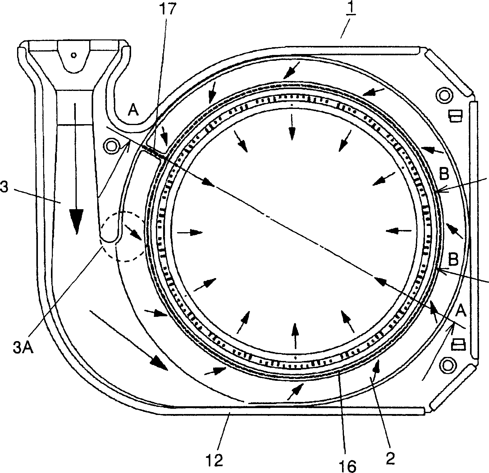
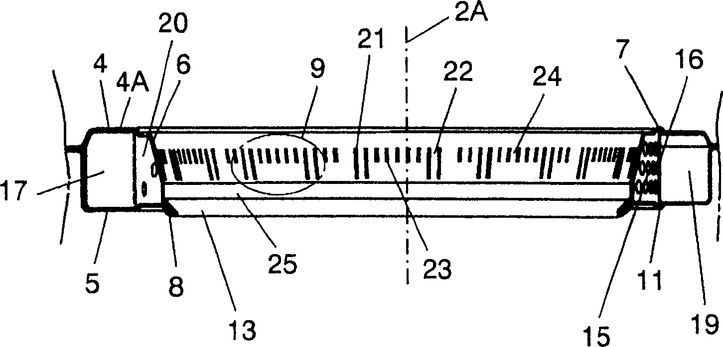
[0045] figure 1 It is a top view of the burner of the embodiment of the present invention;figure 2 Yes figure 1 Sectional view of line A-A; Figure 3A , Figure 3B These are a plan view and a side view of a rectifier body and a barrier body (resistance body), respectively. Figure 4A , Figure 4B They are the expanded view of the rectifier body and the barrier body and the layout drawing of the stamping die; Figure 5 Yes figure 1 Expanded cross-sectional view of part B-B of.

[0046] The burner 1 is composed of a material with excellent heat resistance and corrosion resistance represented by austenitic stainless steel such as SUS304, SUS316, and SUS321, or ferritic stainless steel such as SUS430 and SUS436. The burner 1 is formed by press-forming a metal plate materia...


PUM


Abstract

A combustor comprises a mixing tube for leading in the premixed gas and an annular tube which is communicated with the mixing tube and is arranged with a plurality of flame openings at the inner circumferential surface. The inner side of the annular tube is arranged with a rectifier which allows the passing of the premixed gas and homogenizes the flame distribution at the flame opening, and/or an obstructing body which restrains the backward flow of the premixed gas from the annular tube to the communicating part between the mixing tube and the annular tube.

Description

technical field [0001] The present invention relates to an inward flame type burner using gas, petroleum, etc. as fuel, and a gas stove using the same. Background technique [0002] A conventional inward flame type burner (conventional example 1) is disclosed in, for example, Japanese Patent Laid-Open No. 6-40615. Figure 32 It is a schematic plan view showing the structure of the burner of Conventional Example 1. The mixing tube 201 is connected to the annular tube 202 in a counterclockwise direction and substantially tangentially. A plurality of flame ports 203 are provided on the inner peripheral side of the annular pipe 202 . The cross-sectional area of ​​the annular pipe 202 gradually decreases in the counterclockwise direction from the vicinity of the connection portion with the mixing pipe 201 , that is, the starting end 204 , and becomes the smallest cross-sectional area at the terminal portion 205 of the annular pipe 202 . In this way, all the premixed gas introdu...

Claims


Application Information

Patent Timeline
IPC IPC(8): F23D14/34F23D14/62F24C3/00F24C3/08
Inventor 佐佐田胜视岛田良治柳泽忠
Owner PANASONIC CORP
Why Eureka
Try Eureka