

Demister unit and egr system
A technology of mist eliminator and scrubber, applied in the field of EGR system, can solve problems such as the main body of the reverse flow mist eliminator, and achieve the effect of improving the demisting efficiency
- Summary
- Abstract
- Description
- Claims
- Application Information
AI Technical Summary
Problems solved by technology
Method used
Image

Examples
no. 1 Embodiment approach
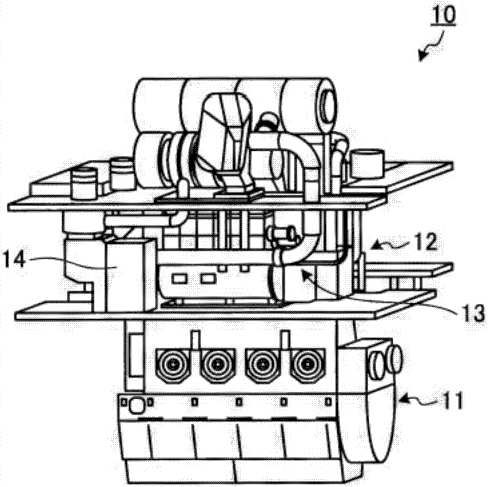
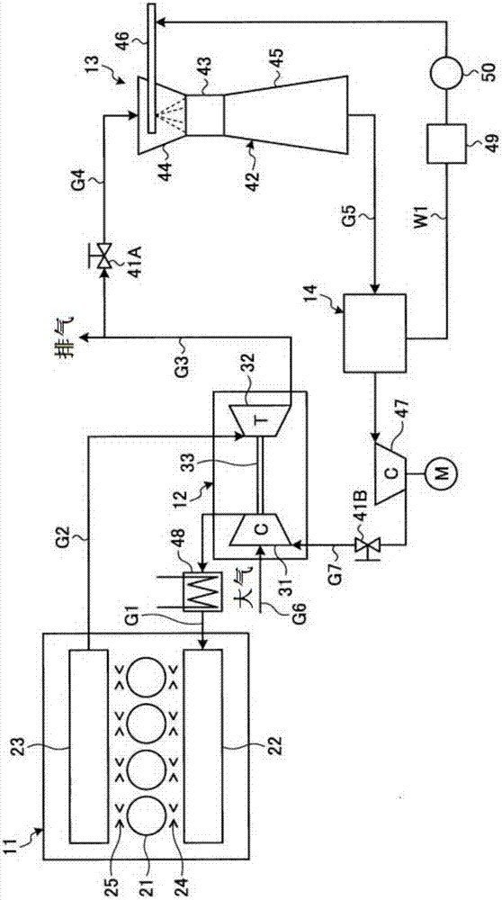
[0051] figure 1It is a schematic diagram showing a diesel engine equipped with an EGR system to which the demister unit of the first embodiment is applied. figure 2 It is a schematic configuration diagram showing the EGR system of the first embodiment.
[0052] In the first embodiment, if figure 1 As shown, the marine diesel engine 10 includes an engine main body 11 , a supercharger 12 , and an EGR system 13 .
[0053] Such as figure 2 As shown, the engine main body 11 is a propulsion engine (main engine) that rotationally drives a propulsion propeller through a propeller shaft (not shown). The engine main body 11 is a single-flow scavenging diesel engine and also a two-stroke diesel engine, so that the flow of intake air and exhaust gas in the cylinder becomes one-way from bottom to top without exhaust residue. The engine main body 11 includes a plurality of cylinders (combustion chambers) 21 through which pistons move up and down, a scavenging manifold 22 communicating...
no. 2 Embodiment approach
[0090] Figure 5 It is a vertical sectional view showing the inlet of the demister unit of the second embodiment. In addition, the same code|symbol is attached|subjected to the member which has the same function as the above-mentioned embodiment, and detailed description is abbreviate|omitted.
[0091] In the second embodiment, if Figure 5 As shown, the demister unit 70 includes a housing 51 , a demister main body 52 , a drain pipe (drain guide) 71 , a drain discharge pipe 72 , and a water storage tank 55 .
[0092] An inlet portion 61 and an outlet portion 62 are formed in the casing 51 , and the demister main body 52 is arranged between the inlet portion 61 and the outlet portion 62 . A drain pipe 71 is provided at the lower part of the demister main body 52, and the drain pipe 71 guides the mist separated from the demister main body 52 downward. The discharge pipe 71 is composed of a straight portion 81 , a first curved portion 82 , and a second curved portion 83 . The...
no. 3 Embodiment approach
[0107] Image 6 It is a longitudinal sectional view showing the inlet of the demister unit of the third embodiment. Figure 7 It is a side view showing the connection portion of the drain tube and the drain tube. In addition, the same code|symbol is attached|subjected to the member which has the same function as the above-mentioned embodiment, and detailed description is abbreviate|omitted.
[0108] In the third embodiment, if Image 6 with Figure 7 As shown, the demister unit 90 includes a housing 51 , a demister main body 52 , a drain pipe (drain guide) 91 , a drain discharge pipe 72 , and a water storage tank 55 .
[0109] An inlet portion 61 and an outlet portion 62 are formed in the casing 51 , and the demister main body 52 is disposed between the inlet portion 61 and the outlet portion 62 . A drain pipe 91 is provided at the lower portion of the demister main body 52 , and the drain pipe 91 guides the mist separated from the demister main body 52 downward. The disc...
PUM
 Abstract
Description
Claims
Application Information