
Air outlet structure of air conditioner, mounting method and air conditioner

A technology for air outlets and air conditioners, applied in the direction of airflow control components, etc., can solve the problems of moldy sealing sponges, low reliability, and airflow turbulence, and achieve the effects of ensuring surface integrity, saving screws, and improving firmness

Inactive Publication Date: 2017-01-11
HISENSE (GUANGDONG) AIR CONDITIONER
View PDF7 Cites 3 Cited by
  • Summary
  • Abstract
  • Description
  • Claims
  • Application Information

AI Technical Summary

Problems solved by technology

The deflector is fixed on the base through screw assembly. In order to increase the positioning and firmness, a through hole is provided on the deflector, and a protrusion matching the hole is provided on the base; during the operation of the air conditioner, the guide Vibration caused by air flow may occur at the flow plate, causing the buckle to fall off from the hole; and for ease of assembly, the size of the hole will be larger than the size of the protrusion, so that after the deflector is assembled, there will be a hole in the hole. A large assembly gap will lead to air flow to a certain extent and even condensation and abnormal sound of thermal expansion and contraction; in order to solve this problem, it is necessary to paste sealing sponge or flocking cloth here, which increases the cost and The process time, and after a long time, the sealing sponge or flocking cloth will become moldy and unhygienic
In addition, the opening of the clamping hole destroys the surface integrity of the exterior surface on the side of the air outlet, which is not beautiful, and the clamping hole is a through hole, which is prone to breakage and has low reliability.

Method used


Image

  • Air outlet structure of air conditioner, mounting method and air conditioner
  • Air outlet structure of air conditioner, mounting method and air conditioner
  • Air outlet structure of air conditioner, mounting method and air conditioner

Examples


Embodiment Construction

[0034] In order to make the purpose, technical solutions and advantages of the embodiments of the present invention more clear, the technical solutions in the embodiments of the present invention will be clearly and completely described below in conjunction with the drawings in the embodiments of the present invention.

[0035] In the description of the present invention, it should be noted that the orientation or positional relationship indicated by the terms "inner", "upper", "lower", "left", "right" etc. is based on the positional relationship shown in the drawings, only It is for the convenience of describing the present invention and simplifying the description, but does not indicate or imply that the referred device or element must have a specific orientation, be constructed and operated in a specific orientation, and thus should not be construed as limiting the present invention. In addition, the terms "first" and "second" are used for descriptive purposes only, and shou...


PUM


Abstract

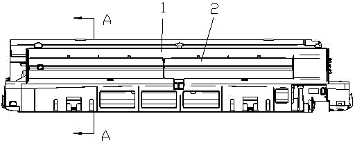
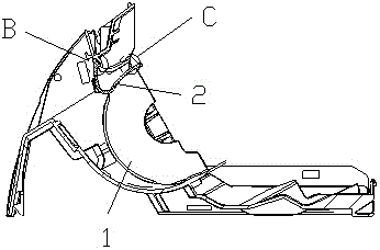
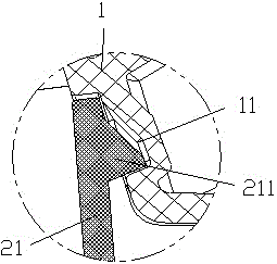
The invention provides an air outlet structure of an air conditioner, a mounting method and the air conditioner. The air outlet structure of the air conditioner comprises a base and a guide plate fixed to the base in a clamped mode. The guide plate comprises a first guide part and a second guide part, and the first guide part and the second guide part are arranged at a certain angle. At least two first buckle assemblies are arranged between the base and the first guide part, and at least two second buckle assemblies are arranged between the base and the second guide part. According to the air outlet structure of the air conditioner, the first guide part and the second guide part which are arranged at a certain angle are fixed to the base in the clamped mode, so that the clamping stress direction of the first buckle assemblies is different from the clamping stress direction of the second buckle assemblies, force from different directions can be borne after combination, and the firmness after fixing is improved; in addition, fixation between the base and the guide plate with screws is omitted, and the assembling efficiency is improved; and furthermore, the first buckle assemblies and the second buckle assemblies are all of a hidden buckle structural form, so that surface integrity of the appearance surface is guaranteed, and the strength of structural components can be improved.

Description

technical field [0001] The invention belongs to the technical field of air conditioners, and in particular relates to an air conditioner air outlet structure, an installation method for the air conditioner air outlet structure, and an air conditioner with the air outlet structure. Background technique [0002] The air outlet structure of the existing wall-mounted air conditioner indoor unit includes a base and a deflector. The deflector is assembled and fixed on the base by screws. In order to increase the positioning and firmness, a through hole is provided on the deflector, and a protrusion matching the hole is provided on the base; during the operation of the air conditioner, the guide Vibration caused by air flow may occur at the flow plate, causing the clip to fall off from the clip hole; and for ease of assembly, the size of the clip hole will be larger than the size of the clip protrusion, so that after the deflector is assembled, there will be a hole in the clip hole...

Claims


Application Information

Patent Timeline
Patent Type & Authority Applications(China)
IPC IPC(8): F24F13/08
CPCF24F13/08
Inventor 吕丹丹朱建国
Owner HISENSE (GUANGDONG) AIR CONDITIONER
Learn More