Driving control method for LED display screen

A technology of LED display and monitoring data, applied in static indicators, instruments, etc., can solve the problems of real-time display, lack of communication connection, limit the separation distance of the sending card of the control system, etc., and achieve the goal of reducing the difficulty of wiring Effect

Active Publication Date: 2017-01-11
XIAN NOVASTAR TECH
View PDF7 Cites 35 Cited by
  • Summary
  • Abstract
  • Description
  • Claims
  • Application Information

AI Technical Summary

Problems solved by technology

[0004] However, although the existing technology proposes the architecture of the wireless LED display system, it does not give any specific implementation methods such as how to establish a communication connection, how to implement screen matching, how to implement data distribution, etc.; in addition, due to the limitations of UWB technology Its effective transmission distance can only be about 5 meters, which seriously limits the separation distance between the sending card of the control system and the cabinet. In addition, UWB technology can only transmit compressed video data, which will bring real-time display problems, namely It takes time to decompress the compressed image data, and there will be a certain delay

Method used


Image

  • Driving control method for LED display screen
  • Driving control method for LED display screen
  • Driving control method for LED display screen

Examples


Embodiment Construction

[0017] In order to make the above objects, features and advantages of the present invention more comprehensible, specific implementations of the present invention will be described in detail below in conjunction with the accompanying drawings.

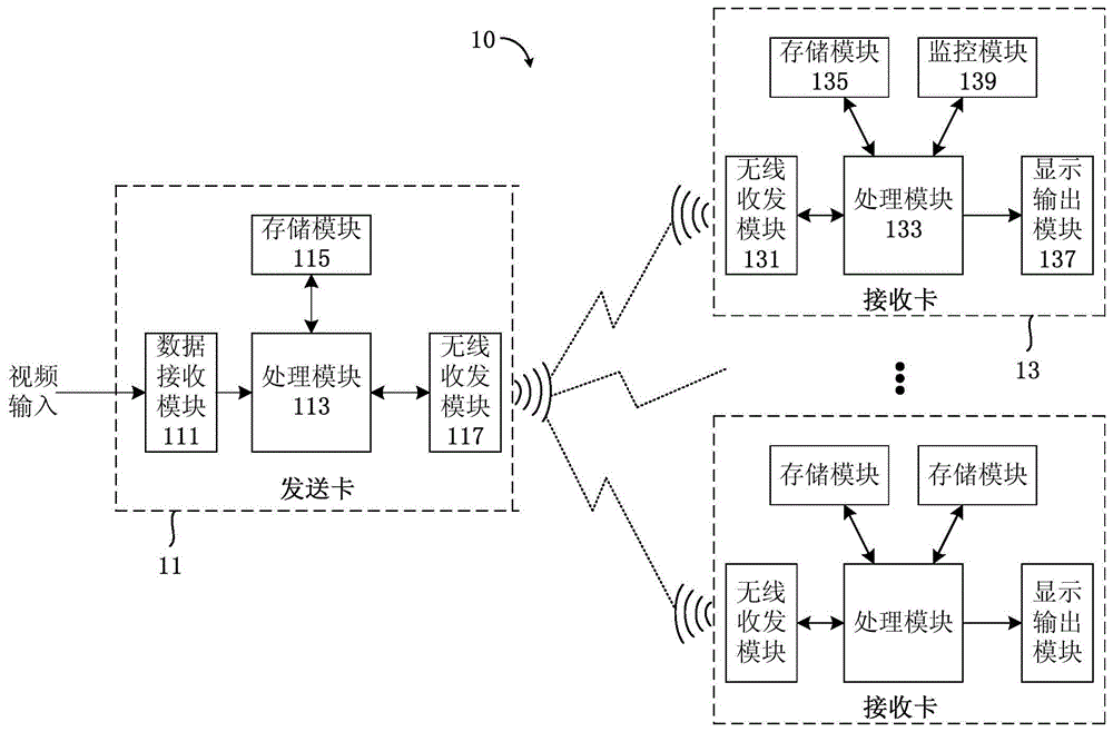
[0018] See figure 1 , which is a partial structural diagram of an LED display system to which an LED display driving control method provided in an embodiment of the present invention is applicable. Such as figure 1 As shown, the LED display system 10 includes a sending card 11 and a plurality of receiving cards 13, and the sending card 11 and a plurality of receiving cards (or scanning control cards) 13 are connected in a wireless manner. It can be understood that the LED display system 10 typically also includes a control computer and a plurality of LED cabinets ( figure 1 not shown in), a plurality of LED cabinets are spliced ​​together to form an LED display screen; the control computer is connected to the sending card 11 to provi...


PUM


Abstract

The invention provides a driving control method for an LED display screen. The method comprises the steps of (a) broadcasting a screen configuration command by a sending card in the wireless mode, and enabling a plurality of receiving cards to control respective loading areas thereof to respectively display the hardware identifier of each receiving card and the loading area information thereof so as to generate a data allocation table, wherein the data allocation table contains a loading position number allocated to each receiving card; (b) storing the data allocation table in the sending card, selectively and wirelessly broadcasting data messages generated based on the data allocation table to the plurality of receiving cards so as to enable the receiving cards to read their respective loading position numbers; and (c) according to the data allocation table, conducting the splitting and packaging process of input video data by the sending card so as to obtain video data packets, wirelessly broadcasting the video data packets to the plurality of receiving cards, and enabling the receiving cards to receive corresponding video data packet and drive their respective loading areas to display the received data according to the hardware identifiers of the receiving cards and the loading position numbers thereof. In this way, a real LED display system in the wireless mode can be realized.

Description

technical field [0001] The invention relates to the technical field of LED display control, in particular to a method for driving and controlling an LED display screen. Background technique [0002] Existing LED display systems are usually divided into synchronous systems and asynchronous systems. Synchronous systems usually include PCs, sending cards, receiving cards and LED displays. Asynchronous systems usually include asynchronous control cards, receiving cards and LED displays. LED displays It can be composed of multiple boxes, and usually a box needs to be equipped with a receiving card. For large-screen display application scenarios, gigabit network or optical fiber connections are used between the cabinets. When the LED display has many cabinets, it often needs to go through multi-level cascading, which brings great harm to the wiring of the LED display. It is very inconvenient; especially in some application environments such as rental LED displays and special-shap...

Claims


Application Information

Patent Timeline
Patent Type & Authority Applications(China)
IPC IPC(8): G09G3/32
Inventor 王伙荣王海栋刘德福
Owner XIAN NOVASTAR TECH
Why Eureka
Try Eureka