Motor vehicle battery

A technology for motor vehicles and batteries, applied in secondary batteries, battery pack components, battery covers/end covers, etc., to achieve the effect of effective heat transfer and reduction of temperature gradients

Inactive Publication Date: 2017-01-11
MAN NUTZFAHRZEUGE AG
View PDF9 Cites 4 Cited by
  • Summary
  • Abstract
  • Description
  • Claims
  • Application Information

AI Technical Summary

Problems solved by technology

However, the additional introduction of cooling fins would drastically alter the existing dimensions and design of the motor vehicle battery 1 , which should however be avoided for reasons of cost.

Method used


Image

  • Motor vehicle battery
  • Motor vehicle battery
  • Motor vehicle battery

Examples


Embodiment Construction

[0031] Identical or functionally equivalent elements are provided with the same reference symbols in all figures and are not described separately.

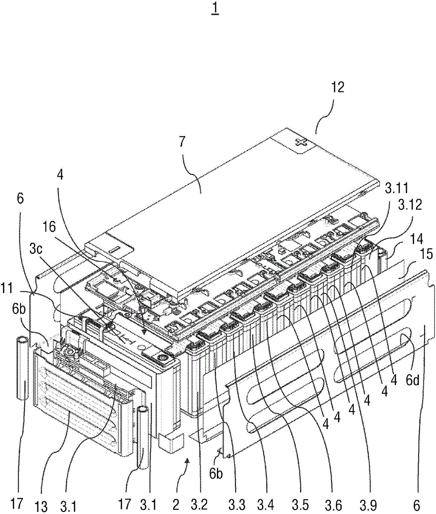
[0032] The basic structure of the motor vehicle battery according to an embodiment of the invention corresponds to figure 1 The structure shown in , so only the special features of the development of the motor vehicle battery are explained below.

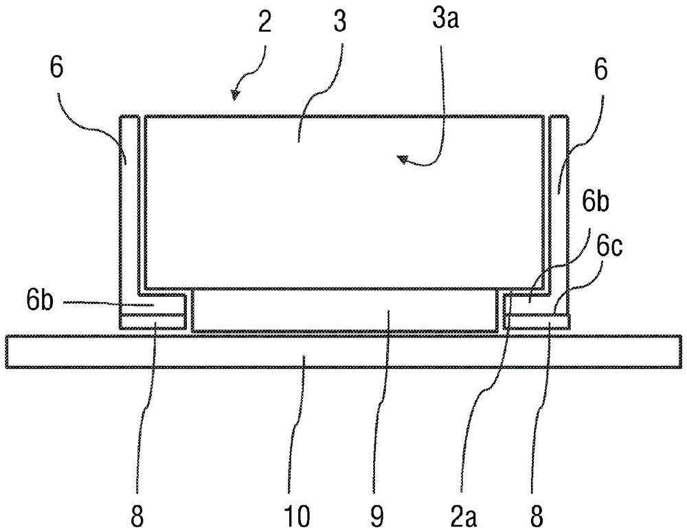
[0033] and figure 1 In contrast to the construction shown in , the recess 6d is not inserted into the two side parts 6 . Rather, the side part 6 has a continuous covering surface. In addition, in figure 1 The paper layer 15 shown in is eliminated.

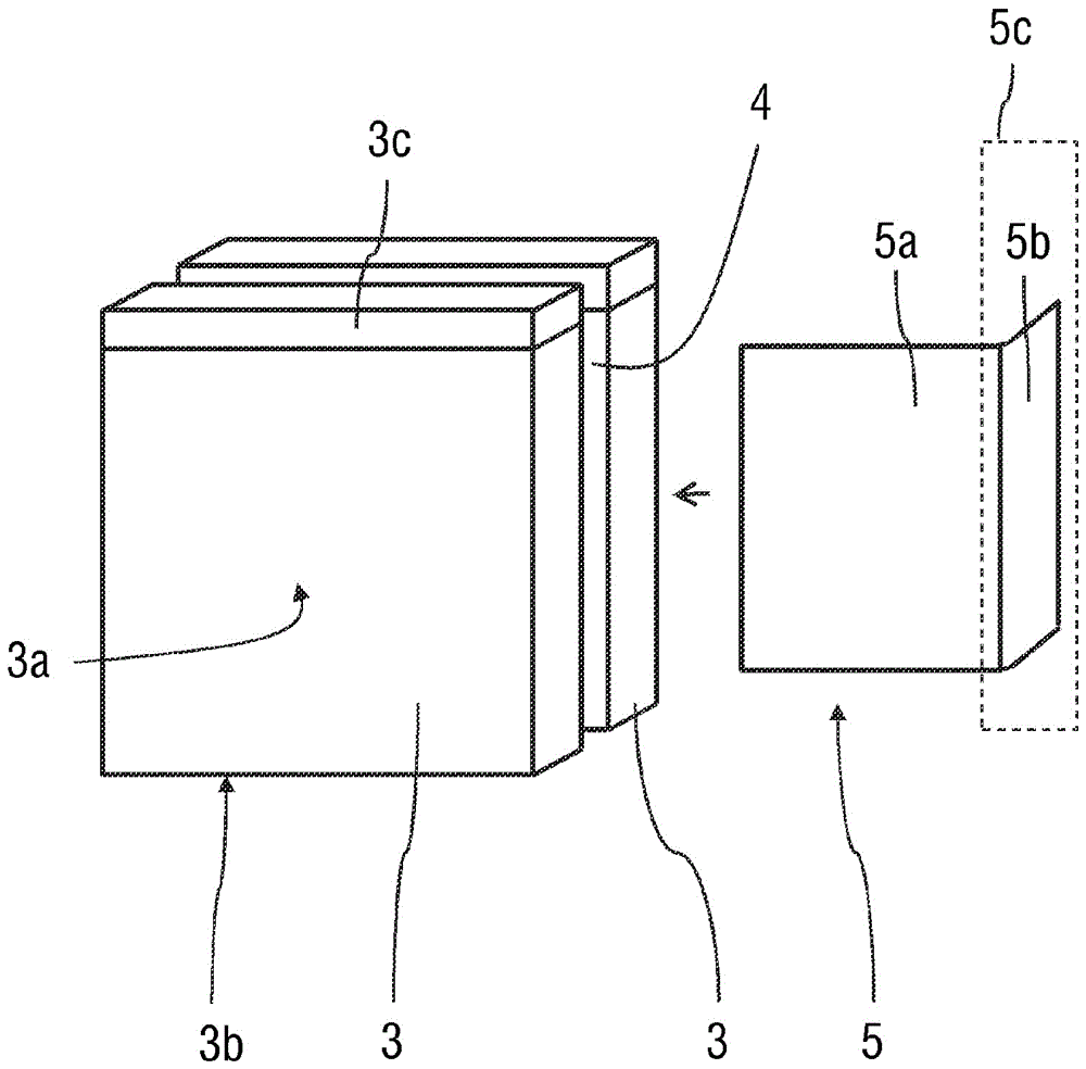
[0034] Another special feature is that, with figure 1 The difference is that the heat-conducting film 5 is now inserted into the intermediate region 4 formed between two adjacent battery cells 3 in each case.

[0035] this is in figure 2 is depicted in a very schematic diagram. figure 2 Two of the twelve battery cells 3 of the batt...


PUM


Abstract

The invention relates to a motor vehicle battery, comprising a battery module (2) which comprises a plurality of battery cells (3) arranged in the manner of a stack, a support structure surrounding the battery module (2), comprising two side parts parallel to the side walls of such a stack of battery cells (3) and (2), arranged between the heat sink and a lower side of the battery module (2), which thermally couples the battery module (2) to the heat sink. In order to improve the heat dissipation of the motor vehicle battery, a thermally conductive element (5) is arranged in at least one of the intermediate regions (4) between two adjacent battery cells (3) and extends from the intermediate region to at least one of the side parts of the support structure Is contacted. The side part, to which the thermally conductive element (5) is thermally contacted, is also thermally coupled to the heat sink.

Description

technical field [0001] The invention relates to a motor vehicle battery according to the preamble of claim 1 . Background technique [0002] Motor vehicle batteries known from practice, such as they are used, for example, as traction accumulators or energy stores in hybrid vehicles or in electric vehicles, typically have one or more battery modules, wherein each battery module has a plurality of stacks A battery cell arranged in a shape. In order to ensure proper operation and to avoid damage to such a motor vehicle battery and to achieve the longest possible service life, the motor vehicle battery must be operated within a defined temperature range. In this case, for example, it is known from the prior art that cooling plates are arranged below the battery modules through which a cooling fluid flows in order to cool the battery modules. [0003] exist figure 1 A motor vehicle battery of this type known from the prior art is shown in a perspective exploded illustration in...

Claims


Application Information

Patent Timeline
IPC IPC(8): H01M10/613H01M10/625H01M10/6555H01M50/209H01M50/271
CPCH01M10/613H01M10/625H01M10/6554B60K1/04H01M50/271H01M50/209H01M10/647H01M10/6555Y02E60/10H01M10/653
Inventor R.布劳恩
Owner MAN NUTZFAHRZEUGE AG
Why Eureka
Try Eureka