Heat dissipation device and application thereof
A heat sink and combined technology, applied in the field of additive manufacturing, can solve the problems of metal bulge deformation, low laser absorption rate, and inability to form metal parts, so as to reduce bulge and improve forming efficiency.
- Summary
- Abstract
- Description
- Claims
- Application Information
AI Technical Summary
Problems solved by technology
Method used
Image
Examples
Embodiment 1
[0058] An additive manufacturing method provided by an embodiment of the present invention includes the following steps:
[0059] Step 1: In the three-dimensional software, select the plane where the bottom of the disc structure of the metal device 1 is located, and the design margin is 0.1mm downward along the axis.
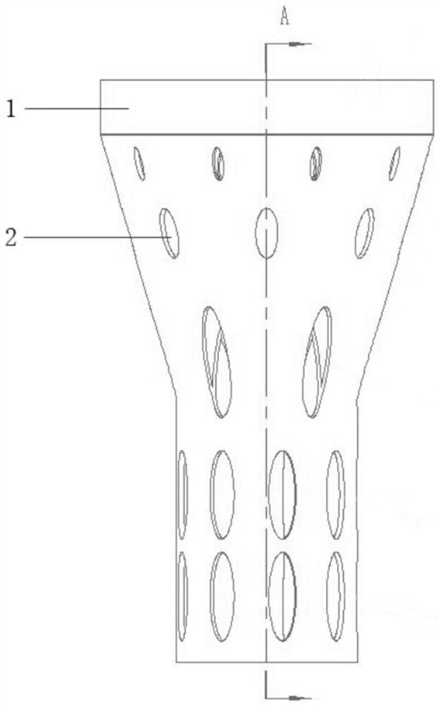
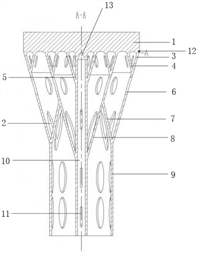
[0060] Step 2: Design the reference groove 12 of the circular wire cutting process based on the bottom of the design margin. The wire cutting process reference groove 12 is 0.1 mm away from the lower bottom surface of the metal device 1 and has a depth of 0.1 mm along the radial direction of the cylindrical heat conducting structure 10.
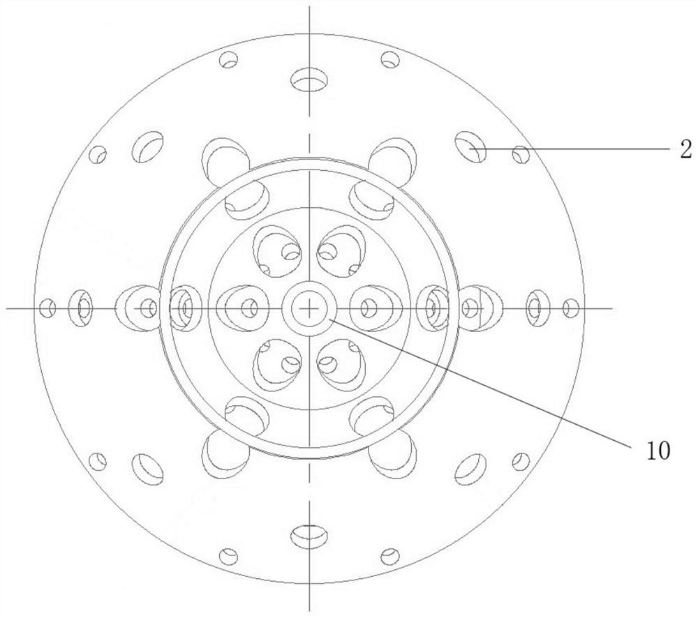
[0061] Step 3: Select the bottom surface of the design margin of the metal device 1, and design a cylindrical heat conducting structure 10 along the axial direction at the center of the disc structure of the metal device 1. The inner diameter of the cylindrical heat conducting structure 10 is 2mm, and the wall thickness of the cylindr...
Embodiment 2
[0073] An additive manufacturing method provided by an embodiment of the present invention includes the following steps:
[0074] Step 1: In the three-dimensional software, select the plane where the bottom of the square plate structure of the metal device 1 is located, and the axial downward margin is 0.2mm as the design margin.
[0075] Step 2: Design the reference groove 12 of the circular wire cutting process based on the bottom of the design margin. The wire cutting process reference groove 12 is 0.2 mm away from the lower bottom surface of the metal device 1 and has a depth of 0.2 mm along the radial direction of the cylindrical heat conducting structure 10.
[0076] Step 3: Select the bottom surface of the metal device 1 with a design margin, and design a cylindrical heat conducting structure 10 along the axial direction at the center of the square plate structure of the metal device 1. The inner diameter of the cylindrical heat conducting structure 10 is 5mm, and the wall thi...
Embodiment 3
[0088] An additive manufacturing method provided by an embodiment of the present invention includes the following steps:
[0089] Step 1: In the three-dimensional software, select the plane where the bottom of the disc structure of the metal device 1 is located, and the allowance is 0.3mm downward along the axis as the design allowance.
[0090] Step 2: Taking the bottom of the design margin as the reference, design the reference groove 12 of the point line cutting process. The wire cutting process reference groove 12 is 0.3 mm away from the lower bottom surface of the metal device 1, and has a depth of 0.3 mm along the radial direction of the cylindrical heat conducting structure 10.
[0091] Step 3: Select the bottom surface of the design margin of the metal device 1, and design a cylindrical heat conducting structure 10 along the axial direction at the center of the disc structure of the metal device 1. The inner diameter of the cylindrical heat conducting structure 10 is 0mm, and...
PUM
| Property | Measurement | Unit |
|---|---|---|
| thickness | aaaaa | aaaaa |
| thickness | aaaaa | aaaaa |
| thickness | aaaaa | aaaaa |
Abstract
Description
Claims
Application Information
 - R&D
- Intellectual Property
- Life Sciences
- Materials
- Tech Scout
- Unparalleled Data Quality
- Higher Quality Content
- 60% Fewer Hallucinations
Browse by: Latest US Patents, China's latest patents, Technical Efficacy Thesaurus, Application Domain, Technology Topic, Popular Technical Reports.
© 2025 PatSnap. All rights reserved.Legal|Privacy policy|Modern Slavery Act Transparency Statement|Sitemap|About US| Contact US: help@patsnap.com


