
Domestic waste gas purification treatment device

A technology for purification treatment and waste gas, which is applied in the direction of combined devices, chemical instruments and methods, and separation of dispersed particles, can solve the problems of reducing the effect of waste gas purification treatment, pollution, and reducing the qualified rate of waste gas discharge, so as to improve the replacement work efficiency and increase Great fluidity, the effect of improving effectiveness

Inactive Publication Date: 2019-02-15
宗诚
View PDF0 Cites 0 Cited by
  • Summary
  • Abstract
  • Description
  • Claims
  • Application Information

AI Technical Summary

Problems solved by technology

[0006] Aiming at the deficiencies of the prior art, the present invention provides a purification treatment device for domestic waste gas, which has a structure for performing liquid neutralization and flow purification on waste gas, effectively improving the treatment efficiency of waste gas and the efficiency of waste gas discharge. The pass rate and other advantages solve the common domestic waste gas treatment equipment. When the waste gas is processed, the waste gas is led to the waste gas treatment pool. Because the water in the pool is not fluid, the waste gas is greatly reduced. The effect of purification treatment has caused serious pollution to the environment due to incomplete waste gas treatment. Due to the single design of common waste gas treatment devices, there is no effective flow treatment of waste gas. While reducing the effect of waste gas treatment, it also greatly reduces The qualified rate of exhaust gas treatment and exhaust gas emission after treatment

Method used


Image

  • Domestic waste gas purification treatment device
  • Domestic waste gas purification treatment device
  • Domestic waste gas purification treatment device

Examples


Embodiment Construction

[0033] The following will clearly and completely describe the technical solutions in the embodiments of the present invention with reference to the accompanying drawings in the embodiments of the present invention. Obviously, the described embodiments are only some, not all, embodiments of the present invention. Based on the embodiments of the present invention, all other embodiments obtained by persons of ordinary skill in the art without making creative efforts belong to the protection scope of the present invention.

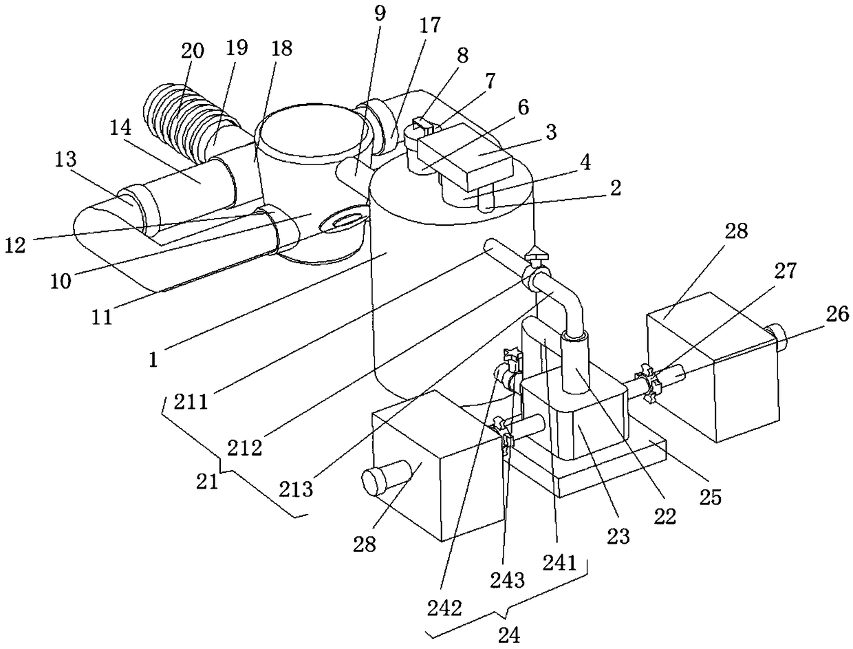
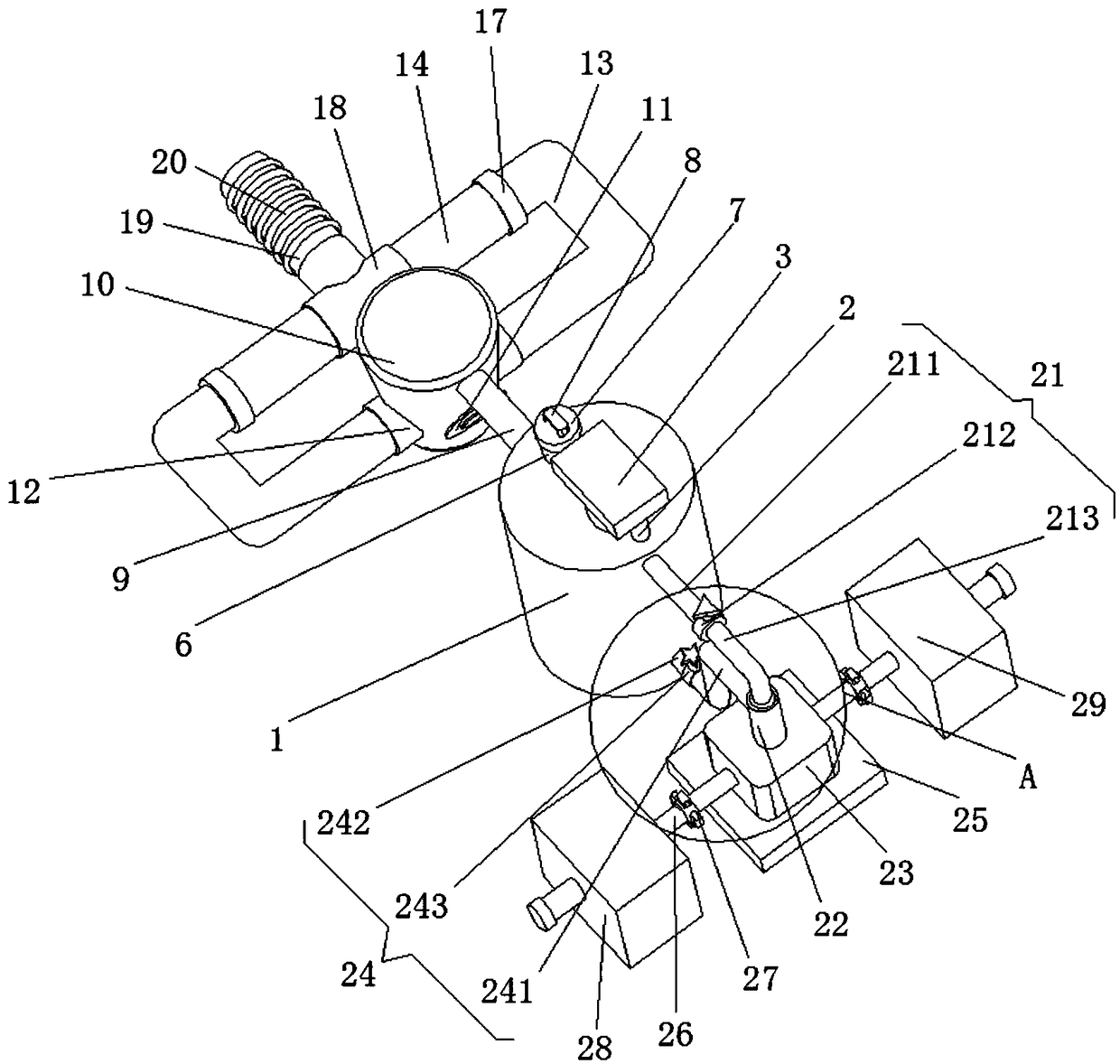
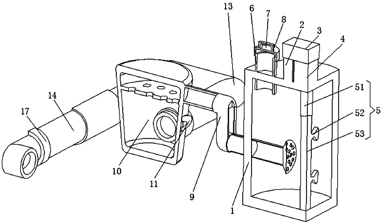
[0034] see Figure 1-7 , a purification treatment device for domestic exhaust gas, including an exhaust gas neutralizer 1, two fixed rods 2 are fixedly installed on the top of the exhaust gas neutralizer 1, and the bottom ends of the two fixed rods 2 are respectively connected to the exhaust gas neutralizer 1 The top of the two fixed rods 2 is fixedly connected to the middle of the left and right sides of the shock absorbing plate 3 respectively, and the middl...


PUM


Abstract

The invention relates to the technical field of waste gas treatment equipment and discloses a domestic waste gas purification treatment device. The purification treatment device comprises a waste gasneutralizer, wherein two fixing rods are fixedly arranged on the top of the waste gas neutralizer; the bottom ends of the two fixing rods are respectively fixedly connected with the top of the waste gas neutralizer; the top ends of the two fixing rods are fixedly connected with the middles of the left and right sides of a vibration damper plate; positions, which are positioned on opposite surfacesof the two fixing rods, of the middle of the lower surface of the vibration damper plate are fixedly connected with a driving motor; the top of a shell of the driving motor is fixedly connected withthe middle of the lower surface of the vibration damper plate. According to the domestic waste gas purification treatment device, due to the effect of a rotating device, waste gases in the middle of the waste gas neutralizer are subjected to flowing purification treatment, so that the liquidity in the waste gas neutralization and purification treatment process is effectively increased, and the condition that the waste gas purification treatment effect is greatly reduced because the neutralization solution in a common waste gas treatment tank does not have liquidity is effectively avoided.

Description

technical field [0001] The invention relates to the technical field of waste gas treatment equipment, in particular to a purification treatment device for domestic waste gas. Background technique [0002] Environmental protection, the full name of environmental protection, refers to the general term of various actions taken by human beings to solve actual or potential environmental problems, coordinate the relationship between human beings and the environment, and ensure the sustainable development of economic society. Its methods and means include engineering technology, administrative management, innovative research and development, as well as legal, economic, publicity and education, etc. [0003] Common environmental protection work includes the treatment of waste gas. Waste gas refers to the poisonous and harmful gases emitted by human beings in the process of production and life, especially in chemical plants, steel plants, pharmaceutical factories, coking plants and o...

Claims


Application Information

Patent Timeline
Patent Type & Authority Applications(China)
IPC IPC(8): B01D53/78B01D53/38B01D50/00
CPCB01D53/38B01D53/78B01D50/20
Inventor 宗诚徐朝晖谢珊珊
Owner 宗诚
Learn More