A cooling device and its application

A heat dissipation device and a combined technology, applied in the field of additive manufacturing, can solve the problems of metal bulge deformation, low laser absorption rate, and metal parts cannot be formed, so as to improve the forming efficiency and reduce the effect of bulge

Active Publication Date: 2022-05-17
TSC LASER TECH DEV BEIJING CO LTD
View PDF0 Cites 0 Cited by
  • Summary
  • Abstract
  • Description
  • Claims
  • Application Information

AI Technical Summary

Problems solved by technology

[0003] In the process of using laser selective melting additive manufacturing technology to print metal devices, due to the low laser absorption rate of the metal itself, a large amount of laser heat is lost to the surrounding powder and formed parts during the laser selective melting process, which makes the metal prone to bulge deformation, which in turn leads to Metal parts cannot be formed by laser selective melting technology

Method used


Image

  • A cooling device and its application
  • A cooling device and its application
  • A cooling device and its application

Examples


Embodiment 1

[0058] An additive manufacturing method provided by an embodiment of the present invention includes the following steps:

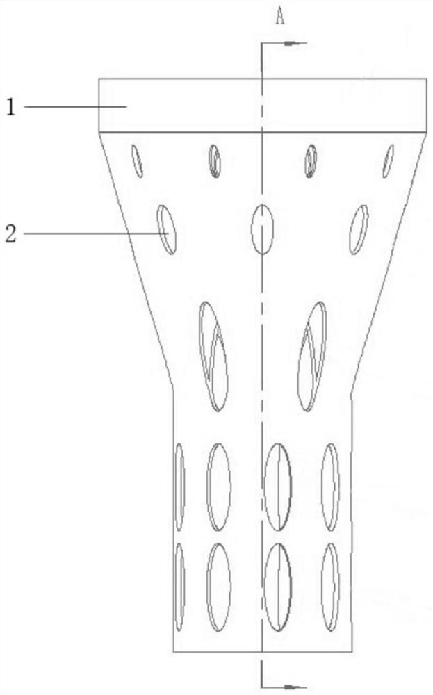
[0059] Step 1: In the 3D software, select the design allowance of 0.1mm downward along the axial direction of the plane where the bottom of the disc structure of the metal device 1 is located.

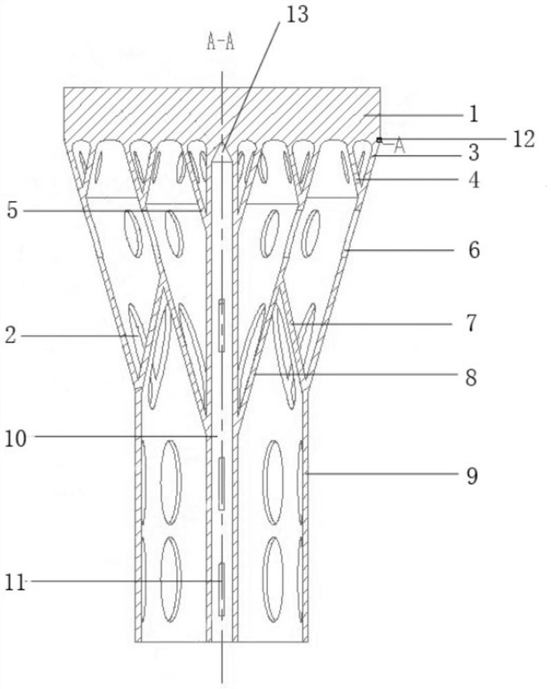
[0060] Step 2: Design the reference groove 12 of the annular wire cutting process based on the bottom of the design margin. The wire cutting process reference groove 12 is 0.1 mm away from the lower bottom surface of the metal device 1 , and the depth along the radial direction of the cylindrical heat conducting structure 10 is 0.1 mm.

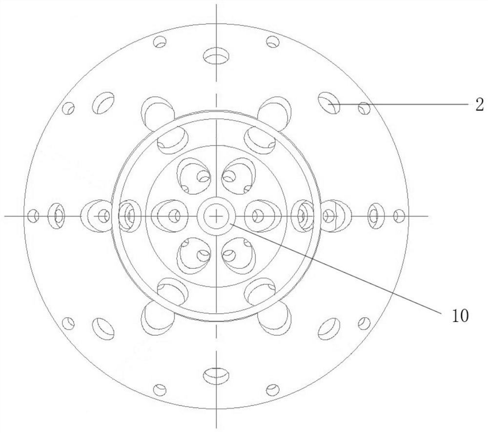
[0061] Step 3: Select the bottom surface under the design margin of the metal device 1, and design a cylindrical heat conduction structure 10 along the axial direction in the center of the disk structure of the metal device 1. The inner diameter of the cylindrical heat conduction structure 10 is 2 mm, and the wall thickness of the ...

Embodiment 2

[0073] An additive manufacturing method provided by an embodiment of the present invention includes the following steps:

[0074] Step 1: In the 3D software, select the design allowance of 0.2mm downward along the axial direction of the plane where the bottom of the metal device 1 square plate structure is located.

[0075] Step 2: Design the reference groove 12 of the annular wire cutting process based on the bottom of the design margin. The wire cutting process reference groove 12 is 0.2 mm away from the lower bottom surface of the metal device 1 , and the depth along the radial direction of the cylindrical heat conducting structure 10 is 0.2 mm.

[0076] Step 3: Select the bottom surface under the design margin of the metal device 1, and design a cylindrical heat-conducting structure 10 in the center of the square plate structure of the metal device 1 along the axial direction. The inner diameter of the cylindrical heat-conducting structure 10 is 5mm, and the wall thickness...

Embodiment 3

[0088] An additive manufacturing method provided by an embodiment of the present invention includes the following steps:

[0089] Step 1: In the 3D software, select a design allowance of 0.3mm downward along the axial direction of the plane where the bottom of the disk structure of metal device 1 is located.

[0090] Step 2: Based on the bottom of the design margin, design the reference groove 12 for the point-shaped line cutting process. The wire cutting process reference groove 12 is 0.3 mm away from the lower bottom surface of the metal device 1 , and the depth along the radial direction of the cylindrical heat conducting structure 10 is 0.3 mm.

[0091] Step 3: Select the bottom surface under the design margin of the metal device 1, and design a cylindrical heat conduction structure 10 along the axial direction in the center of the disk structure of the metal device 1. The inner diameter of the cylindrical heat conduction structure 10 is 0 mm, and the wall thickness of the...


PUM

PropertyMeasurementUnit
thicknessaaaaaaaaaa
thicknessaaaaaaaaaa
thicknessaaaaaaaaaa

Abstract

The invention discloses a heat dissipation device and its application, relates to the technical field of additive manufacturing, and solves the problems of deformation and swelling of printed metal devices. The heat dissipation device includes: a heat conduction structure, at least one first heat conduction hole opened on the heat conduction structure, and a cylindrical heat conduction structure. The heat conduction structure is fixedly connected with the cylindrical heat conduction structure, and the heat conduction structures are distributed in a ring around the cylindrical heat conduction structure. The application of the heat dissipation device in additive manufacturing includes the heat dissipation device mentioned in the above technical solution. The heat dissipation device provided by the present invention is used for disposing on the bottom of the metal device in the additive manufacturing process so as to dissipate heat and support the metal device in the printing process.

Description

technical field [0001] The invention relates to the technical field of additive manufacturing, and in particular, to a heat dissipation device and an application thereof. Background technique [0002] Selective Laser Melting SLM (Selective Laser Melting) additive manufacturing technology uses metal powder as raw material. According to the layered slice information of the 3D CAD model of the molded part, the scanning system controls the laser beam to act on the metal powder in the area to be molded to melt the powder. , after cooling, it is formed. After scanning one layer, the worktable is lowered to a certain height, and then a layer of powder is spread, and it is melted, and it accumulates repeatedly until the entire metal device is formed. Laser selective melting metal 3D printing can directly fabricate metal devices, which has outstanding advantages. [0003] In the process of printing metal devices using laser selective melting additive manufacturing technology, due to...

Claims


Application Information

Patent Timeline
Patent Type & Authority Patents(China)
IPC IPC(8): B22F3/105B33Y30/00
CPCB33Y30/00Y02P10/25
Inventor 刘普祥刘斌李会敏李广生李澄
Owner TSC LASER TECH DEV BEIJING CO LTD
Why Eureka
Try Eureka