OAM test method and equipment for a communication system
A test method and technology of test equipment, applied in the field of communication, can solve the problems of inability to synchronize the OAM function test workload, prone to errors in operation and judgment, and cumbersome test steps.
- Summary
- Abstract
- Description
- Claims
- Application Information
AI Technical Summary
Problems solved by technology
Method used
Image
Examples
example 1
[0110] Example 1: Testing the temporal degradation output function of the system under test.
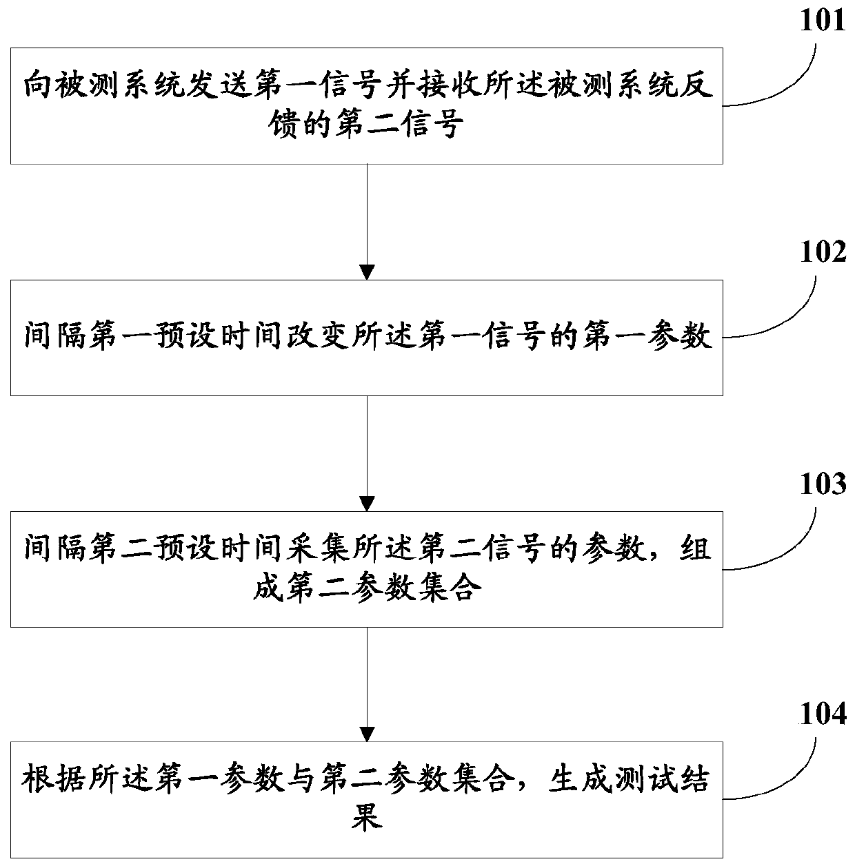
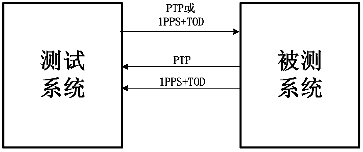
[0111] The test system stores the parameter mapping relationship of different time interface protocols. The test system can support the output and input of two time interfaces, PTP and 1PPS+TOD, and automatically change one of the parameters of the first signal output by the test system to test the output of the system under test. The signal of the second signal changes. If the output and input are different time interfaces, it can test whether the parameters of another time interface change according to the mapping relationship, and automatically give the result of whether the test passes.
[0112] see image 3 , the test system outputs the first signal to the system under test, and at the same time collects the second signal output by the system under test, automatically changes the parameter ClockClass or second pulse state of the first signal of the test system, and analyzes whe...
example 2
[0117] Example 2: Test the function of selecting sources for different time interfaces of the device under test.
[0118] The test system supports the automatic test of the source selection function of different time interfaces of the equipment. The test system stores the parameter mapping relationship of different time interface protocols, outputs the signals of two time interfaces at the same time, automatically changes the parameters of one of the output time interfaces, and causes the device time source to change. The test system passes the test output of the system under test. The parameters in the signal (PTP, 1PPS+TOD) automatically analyze whether the selected source of the system under test changes through the parameters, and automatically give the result of whether the test is passed or not.
[0119] see Figure 4 , the test system sends the first signal to the system under test, that is, the PTP and 1PPS+TOD time signal; at the same time, it obtains the second sign...
example 3
[0131] Example 3: Test the leap second handling functionality of the system under test.
[0132] see Figure 5 , the test system sends the first signal to the system under test, that is, the PTP and 1PPS+TOD time signal; at the same time, it obtains the second signal fed back by the system under test, that is, the PTP and 1PPS+TOD time signal. Automatically change the parameter currentUtcOffset of the PTP signal in the first signal or Leap Seconds in the 1PPS+TOD signal, and automatically analyze whether the leap second of the second signal changes with the output signal (the parameter currentUtcOffset of the PTP output signal or the 1PPS+TOD output signal Leap Seconds). The test system supports the conversion correspondence between the parameters currentUtcOffset and Leap Seconds, and the value of currentUtcOffset=the value of Leap Seconds+19. The specific test steps are as follows:
[0133] Step 1: The test system sends the PTP time signal and the 1PPS+TOD time signal to ...
PUM
 Abstract
Description
Claims
Application Information
 - R&D
- Intellectual Property
- Life Sciences
- Materials
- Tech Scout
- Unparalleled Data Quality
- Higher Quality Content
- 60% Fewer Hallucinations
Browse by: Latest US Patents, China's latest patents, Technical Efficacy Thesaurus, Application Domain, Technology Topic, Popular Technical Reports.
© 2025 PatSnap. All rights reserved.Legal|Privacy policy|Modern Slavery Act Transparency Statement|Sitemap|About US| Contact US: help@patsnap.com


