Thin heat dissipating device

A heat dissipation device and heat dissipation fin technology, which is applied in cooling/ventilation/heating transformation, instruments, electrical digital data processing, etc., can solve the problems of accumulated heat, insufficient heat dissipation of the vapor chamber, and difficulty in vapor chamber blowing, etc., to achieve enhanced Heat dissipation efficiency, hard texture and light weight effect

Inactive Publication Date: 2017-01-11
CHAUN CHOUNG TECH
View PDF5 Cites 6 Cited by
  • Summary
  • Abstract
  • Description
  • Claims
  • Application Information

AI Technical Summary

Problems solved by technology

[0004] However, the above-mentioned heat dissipation device has the following disadvantages. Because the airflow of the fan is mainly concentrated on the heat dissipation fins, it is not easy to concentrate on the vapor chamber, so most of the vapor chambers rely on the heat dissipation fins to dissipate heat, causing the vapor chamber to easily dissipate heat. If it is not enough, it will accumulate heat, which will not effectively improve the heat dissipation efficiency of the heat sink

Method used


Image

  • Thin heat dissipating device
  • Thin heat dissipating device
  • Thin heat dissipating device

Examples


Embodiment Construction

[0049] The detailed description and technical content of the present invention will be described as follows with accompanying drawings, but the attached drawings are only for illustration purposes and are not intended to limit the present invention.

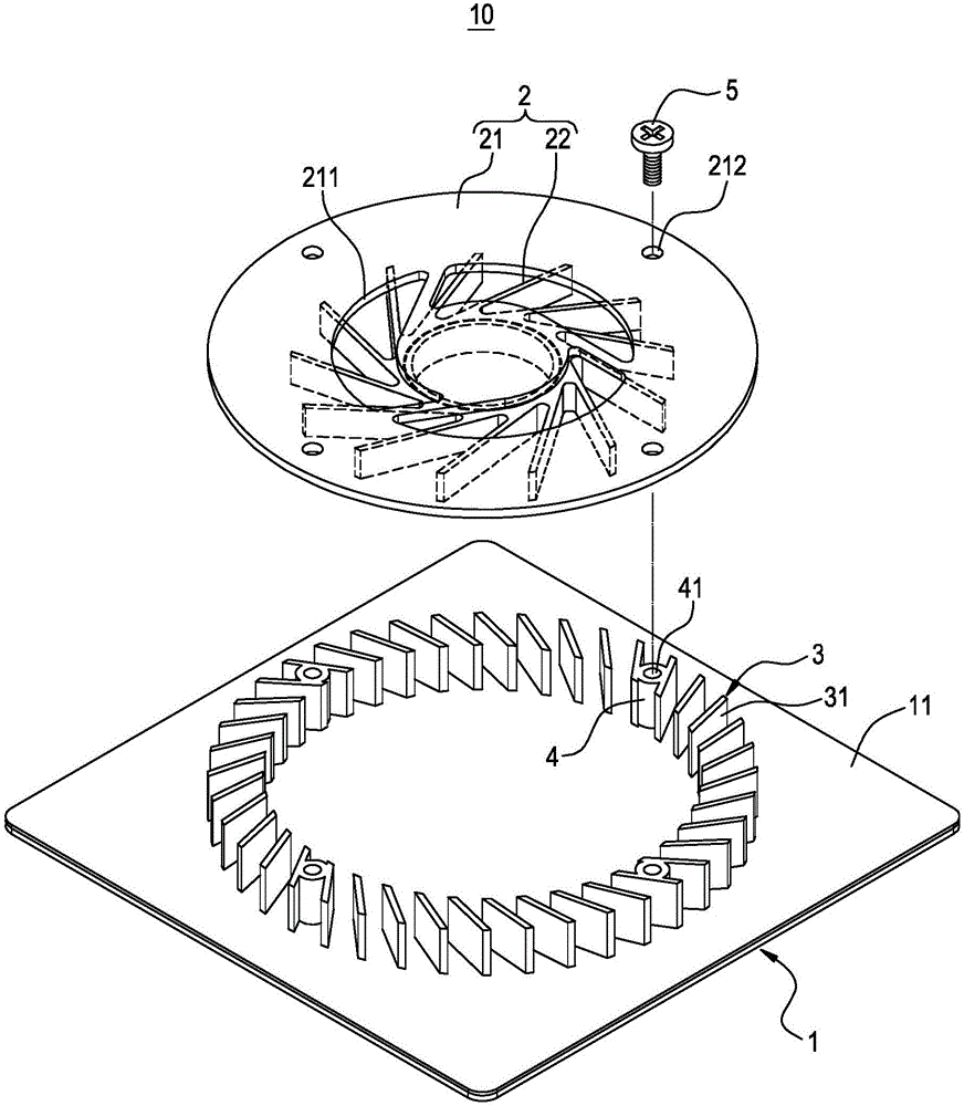
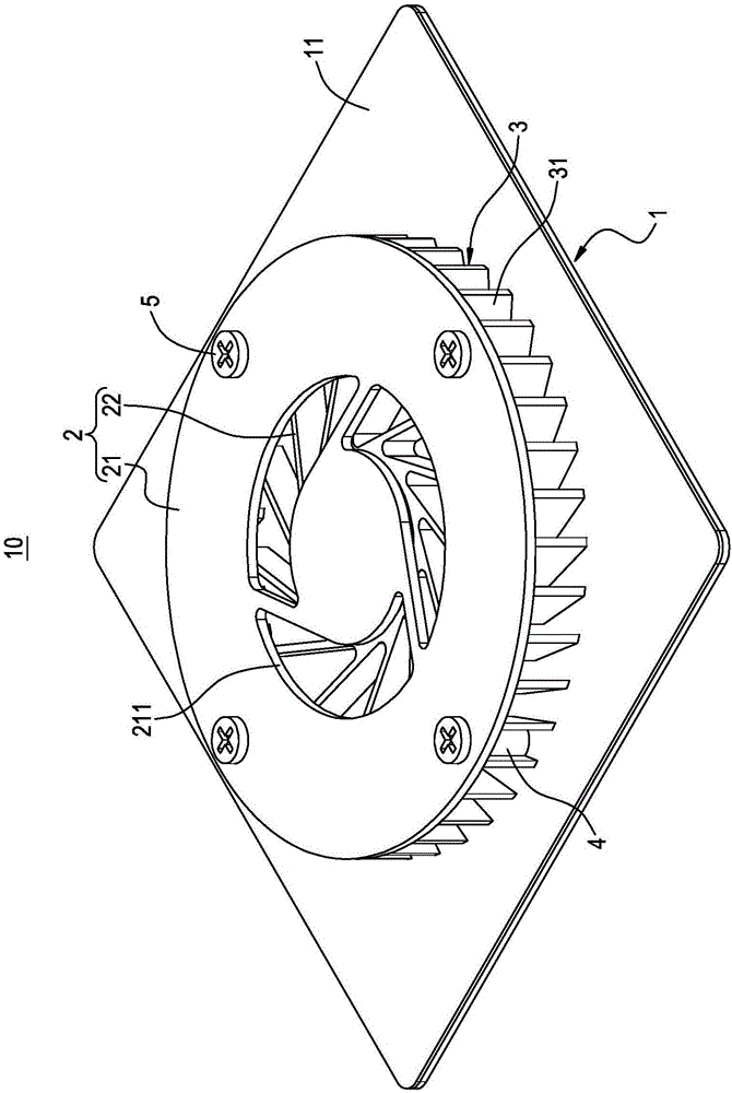
[0050] Please refer to Figure 1 to Figure 4 As shown, the present invention provides a thinner heat dissipation device. The thinner heat dissipation device 10 mainly includes a vapor chamber 1 , a fan module 2 and an annular fin set 3 .

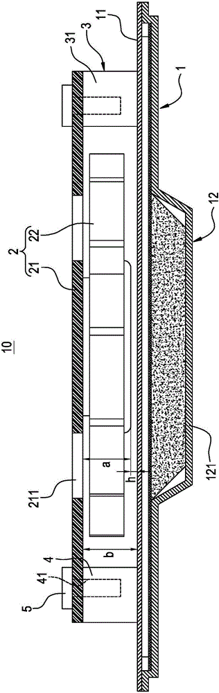
[0051] Such as Figure 1 to Figure 4 As shown, the vapor chamber 1 has a condensing surface 11 and a heating surface 12 opposite to each other. The heating surface 12 has a protruding portion 121 , and the protruding portion 121 is used for bonding with the heating element 100 .

[0052] Such as Figure 1 to Figure 3 As shown, the fan module 2 and the vapor chamber 1 are fixedly connected to each other. The fan module 2 includes a cover plate 21 and a fan 22 installed under the cover plate 21...


PUM


Abstract

The invention discloses a thin heat dissipating device comprising a uniform-temperature plate, a fan module and an annular fin group. The uniform-temperature plate has a condensing surface. The fan module and the uniform-temperature plate are fixedly connected with each other. The fan module includes a cover plate and a fan mounted under the cover plate, and the cover plate is provided with an air vent corresponding to the fan. The annular fin group is clamped between the cover plate and the condensing surface, and the annular fin group annularly surrounds the outer periphery of the fan. Thus, the fan is accommodated in a space formed by the cover plate, the condensing surface and the annular fin group and can blow air directly to the uniform-temperature plate and the annular fin group, and therefore, the heat dissipating efficiency of the thin heat dissipating device is improved.

Description

technical field [0001] The invention relates to a heat dissipation device, in particular to a thinned heat dissipation device. Background technique [0002] As 3C products are widely used by the public, the computing speed and performance of electronic components (such as central processing units) in 3C products are continuously improved, resulting in higher and higher heat generated by electronic components. However, if the electronic components maintain high temperature It is easy to affect the computing efficiency, so the industry will use a heat sink to help the electronic components dissipate heat. [0003] Traditional cooling devices mainly include a vapor chamber, multiple heat dissipation fins, and a fan. One side of the vapor chamber is attached to electronic components, and the other side is connected to heat dissipation fins. The fan is then configured corresponding to the heat dissipation fins, so that the electronic components The heat is transferred from the v...

Claims


Application Information

Patent Timeline
Patent Type & Authority Applications(China)
IPC IPC(8): H05K7/20G06F1/20
Inventor 吴建兴邱士伦
Owner CHAUN CHOUNG TECH
Why Eureka
Try Eureka