Working fluid contact cooling system for server
A cooling system and server technology, applied in the direction of cooling/ventilation/heating transformation, electrical components, electrical equipment construction parts, etc., can solve the problems of equipment performance, safety and service life, so as to save cycle power consumption and improve utilization High efficiency, reliable and durable replacement and maintenance effect
- Summary
- Abstract
- Description
- Claims
- Application Information
AI Technical Summary
Problems solved by technology
Method used
Image
Examples
Embodiment 1
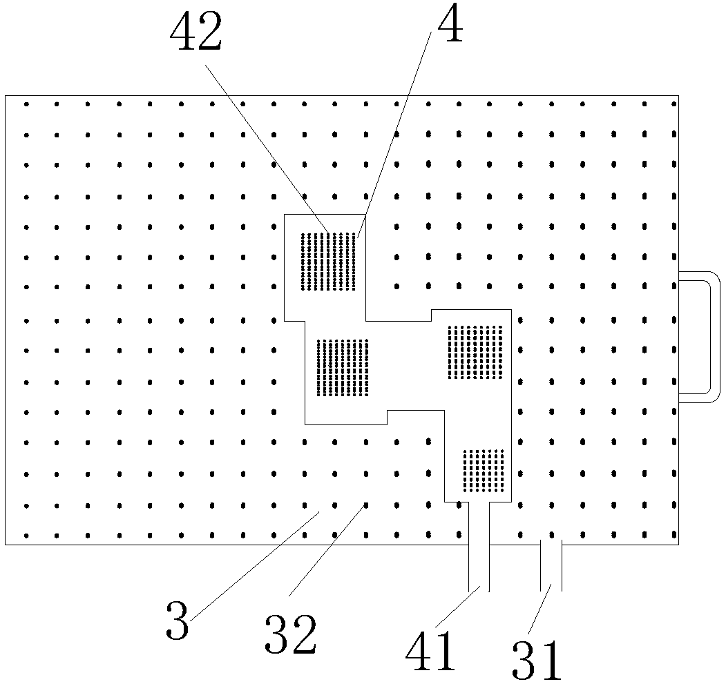
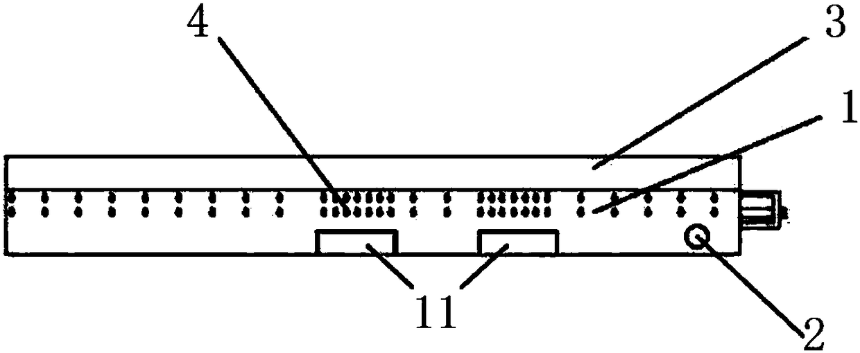
[0037] see figure 1 and figure 2 , the present invention provides a working fluid contact cooling system for a server, which includes a spray area and a server working area 1 arranged below the spray area, and the liquid working fluid passes through the spray area and first contacts with the server The working area 1 contacts, and then flows back through the return hole 2,
[0038] The spray area includes a first spray chamber 3 and a second spray chamber 4 with a higher spray density than the first spray chamber 3, the first spray chamber 3 and the second spray chamber 4 disconnected,
[0039] The first spray chamber 3 includes a first liquid inlet hole 31 and a plurality of first spray devices 32, the first spray devices 32 correspond to the normal temperature area of the server working area 1,
[0040] The second shower chamber 4 includes a second liquid inlet hole 41 and at least one second shower device 42 , and the second shower device 42 corresponds to the high te...
Embodiment 2
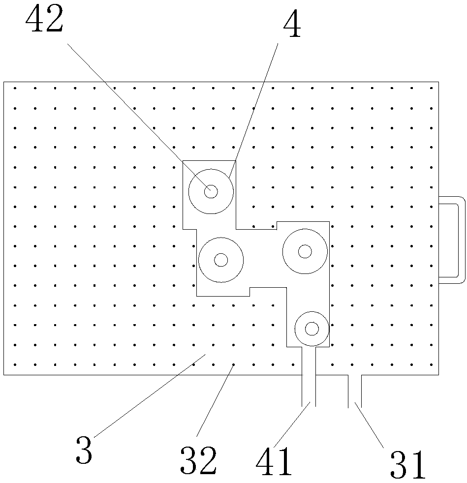
[0051] see image 3 and Figure 4 , the present invention provides a working fluid contact cooling system for a server, which includes a spray area and a server working area 1 arranged below the spray area, and the liquid working fluid passes through the spray area and first contacts with the server The working area 1 contacts, and then flows back through the return hole 2,
[0052] The spray area includes a first spray chamber 3 and a second spray chamber 4 with a higher spray density than the first spray chamber 3, the first spray chamber 3 and the second spray chamber 4 disconnected,
[0053] The first spray chamber 3 includes a first liquid inlet hole 31 and a plurality of first spray devices 32, the first spray devices 32 correspond to the normal temperature area of the server working area 1,
[0054] The second shower chamber 4 includes a second liquid inlet hole 41 and at least one second shower device 42 , and the second shower device 42 corresponds to the high te...
Embodiment 3
[0065] see Figure 5 , Figure 6 , Figure 7 and Figure 8 , the present invention provides a working fluid contact cooling system for a server, which includes a spray area and a server working area 1 arranged below the spray area, and the liquid working fluid passes through the spray area and first contacts with the server The working area 1 contacts, and then flows back through the return hole 2,
[0066] The spray area includes a first spray chamber 3 and a second spray chamber 4 with a higher spray density than the first spray chamber 3, the first spray chamber 3 and the second spray chamber 4 disconnected,
[0067] The first spray chamber 3 includes a first liquid inlet hole 31 and a plurality of first spray devices 32, the first spray devices 32 correspond to the normal temperature area of the server working area 1,
[0068] The second shower chamber 4 includes a second liquid inlet hole 41 and at least one second shower device 42 , and the second shower device 42...
PUM
 Abstract
Description
Claims
Application Information
 - R&D
- Intellectual Property
- Life Sciences
- Materials
- Tech Scout
- Unparalleled Data Quality
- Higher Quality Content
- 60% Fewer Hallucinations
Browse by: Latest US Patents, China's latest patents, Technical Efficacy Thesaurus, Application Domain, Technology Topic, Popular Technical Reports.
© 2025 PatSnap. All rights reserved.Legal|Privacy policy|Modern Slavery Act Transparency Statement|Sitemap|About US| Contact US: help@patsnap.com


