A turn-over device applied to a pipe turn-over frame

A technology of flapping and pipe materials, which is applied in metal processing and other directions, can solve the problems of inaccurate index control, surface wear of plastic material pipes, single function, etc., and achieve the effect of improving practicability and turning stability

Active Publication Date: 2018-04-24
ANHUI JIELANTE NEW MATERIAL CO LTD
View PDF5 Cites 0 Cited by
  • Summary
  • Abstract
  • Description
  • Claims
  • Application Information

AI Technical Summary

Problems solved by technology

In traditional production, manual unloading is generally used. Usually, most pipe products, especially pipes with special application requirements, need to be inspected and turned over in all directions. At this time, manual unloading not only has high labor intensity and high index The control is not precise, and it is not conducive to the improvement of the efficiency of the efficient production of the production line
[0003] At the same time, during the weighing process of manual operation, the surface of the plastic tube is prone to wear due to friction, impact, etc., which affects sales and brings unnecessary economic loss to the manufacturer.
[0004] The existing pipe turnover racks on the market all have a single function, and most of them are only used for supporting and turning in the processing of pipes of a single specification, and cannot have the function of automatic turning. The present invention aims to develop a The turning device of the rack, on the basis of the original turning rack, through the introduction of the mechanism design of the automatic turning device, the automatic operation of the multi-angle turning operation of the pipe on the turning rack can be realized, and the detection and processing of the pipe can be improved. flipping efficiency

Method used


Image

  • A turn-over device applied to a pipe turn-over frame
  • A turn-over device applied to a pipe turn-over frame

Examples


Embodiment Construction

[0019] In order to make the object, technical solution and advantages of the present invention clearer, the present invention will be further described in detail below in conjunction with the accompanying drawings and embodiments. It should be understood that the specific embodiments described here are only used to explain the present invention, not to limit the present invention.

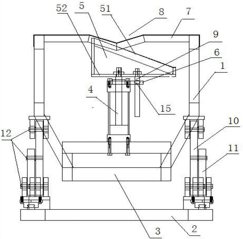
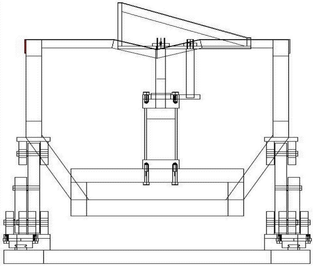
[0020] First, please refer to Figure 1-2 , the present invention provides a turning device applied to a pipe turning frame, including a support frame, characterized in that: the support frame includes an upper frame 1 and a lower frame 2, the lower end of the upper frame 1 is provided with a base 3, and the base 3 is fixed A turning mechanism (not marked in the figure) is provided, and the turning mechanism includes a hydraulic cylinder 4, and the output shaft of the hydraulic cylinder 4 is fixed with a support flap, and the support flap 5 includes a base plate 52 and a support panel 51, The supp...


PUM


Abstract

A pipe turning frame device comprises a supporting frame. The supporting frame comprises an upper frame body and an underframe body. A base is arranged at the lower end of the upper frame body. A turning frame mechanism is fixedly arranged on the base. The turning frame mechanism comprises a hydraulic cylinder. A supporting turning plate is fixedly arranged on an output shaft of the hydraulic cylinder. The supporting turning plate comprises a bottom plate and a supporting panel. The supporting panel is arranged obliquely along the horizontal plane. A balance fulcrum bar is arranged in the position, on one side of the output shaft of the hydraulic cylinder, of the bottom plate. A square supporting plate is fixedly arranged on the upper end face of a sleeve of the hydraulic cylinder. A through hole is formed in the lateral portion of the square supporting plate. The balance fulcrum bar movably penetrates through the through hole in the square supporting plate. Through cooperation with a stable supporting platform with a V-shaped supporting part, a stable automatic turning frame function can be achieved; and through the height adjustment structure design, the pipe turning frame device can be combined with a turning plate frame device to be applied, the turning frame function can also be achieved independently, and the practicability is improved. The turning frame is stable in turning, the turning angle can be controlled through telescopic height of the hydraulic cylinder, and the pipe turning frame device can be suitable for various pipe product supports and production line functional improvement.

Description

technical field [0001] The present invention relates to the technical field of pipe production and processing equipment, and more specifically, to a turning device applied to a pipe turning frame. Background technique [0002] The pipe turning device is generally used at the end of the manufacturing line of various pipe products to complete the processing, cutting and unloading of pipe products. In traditional production, manual unloading is generally used. Usually, most pipe products, especially pipes with special application requirements, need to be inspected and turned over in an all-round way. At this time, manual unloading not only has high labor intensity and high index The control is not precise, and it is not conducive to the improvement of the efficiency of the efficient production of the production line. [0003] At the same time, during the weighing process of manual operation, the surface of the plastic tube is prone to wear due to friction, impact and other con...

Claims


Application Information

Patent Timeline
Patent Type & Authority Patents(China)
IPC IPC(8): B26D7/27
CPCB26D7/27
Inventor 刘俊峰刘文江万刚
Owner ANHUI JIELANTE NEW MATERIAL CO LTD
Why Eureka
Try Eureka