Holding element and functional assembly with the holding element

A technology for retaining components and functional components, applied in the direction of connecting components, mechanical equipment, etc., can solve the problems of shortened mold life, increased molding cost, poor quality of parts, etc.

Inactive Publication Date: 2020-04-28
SENSATA TECHNOLOGIES INC
View PDF4 Cites 0 Cited by
  • Summary
  • Abstract
  • Description
  • Claims
  • Application Information

AI Technical Summary

Problems solved by technology

Or, in order to solve the above contradiction, it is also possible to use forced ejection for demoulding. In this case, it is necessary to allow a small overlap between the mold and the holding element in the clamping area or to set an adjustable Broken lip, but this not only increases molding cost and poor part quality due to forced ejection, but also reduces mold life

Method used


Image

  • Holding element and functional assembly with the holding element
  • Holding element and functional assembly with the holding element
  • Holding element and functional assembly with the holding element

Examples


Embodiment Construction

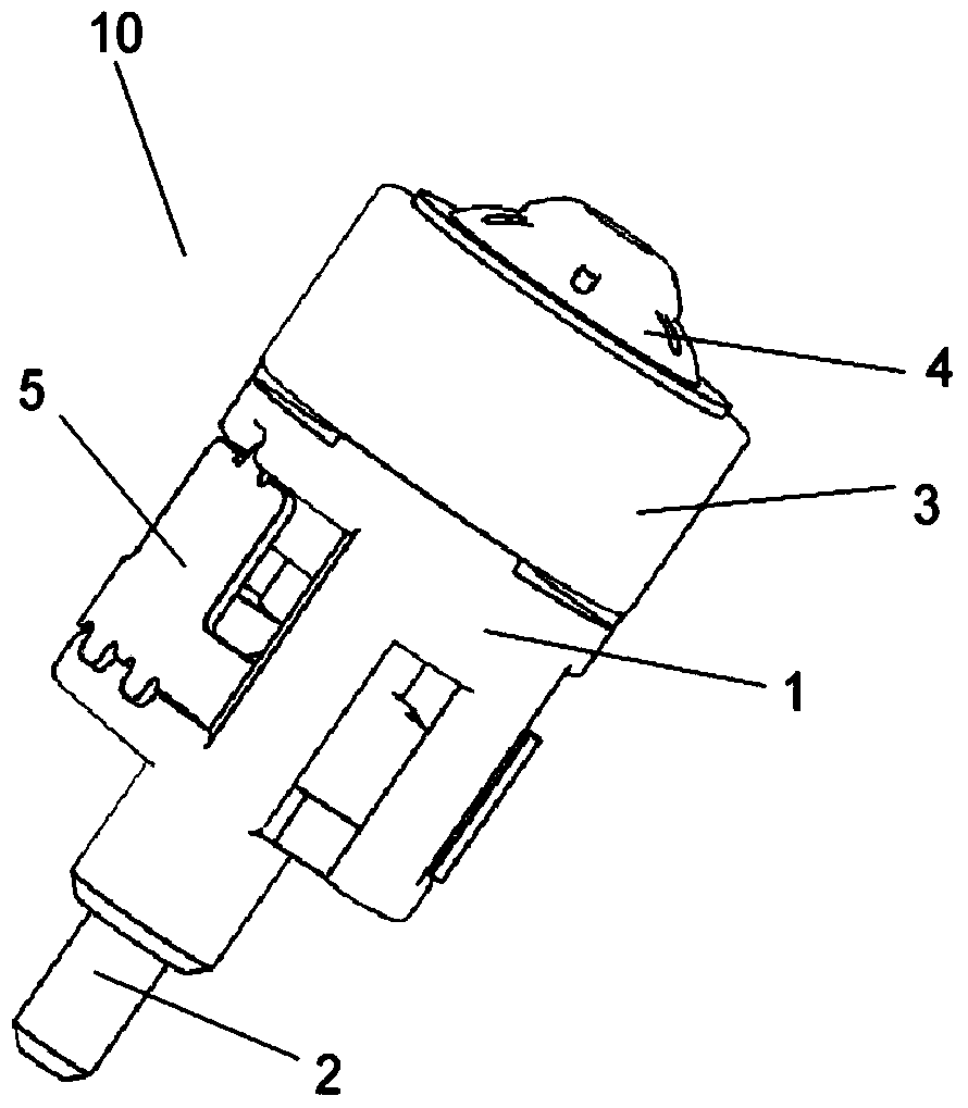
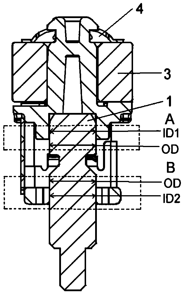
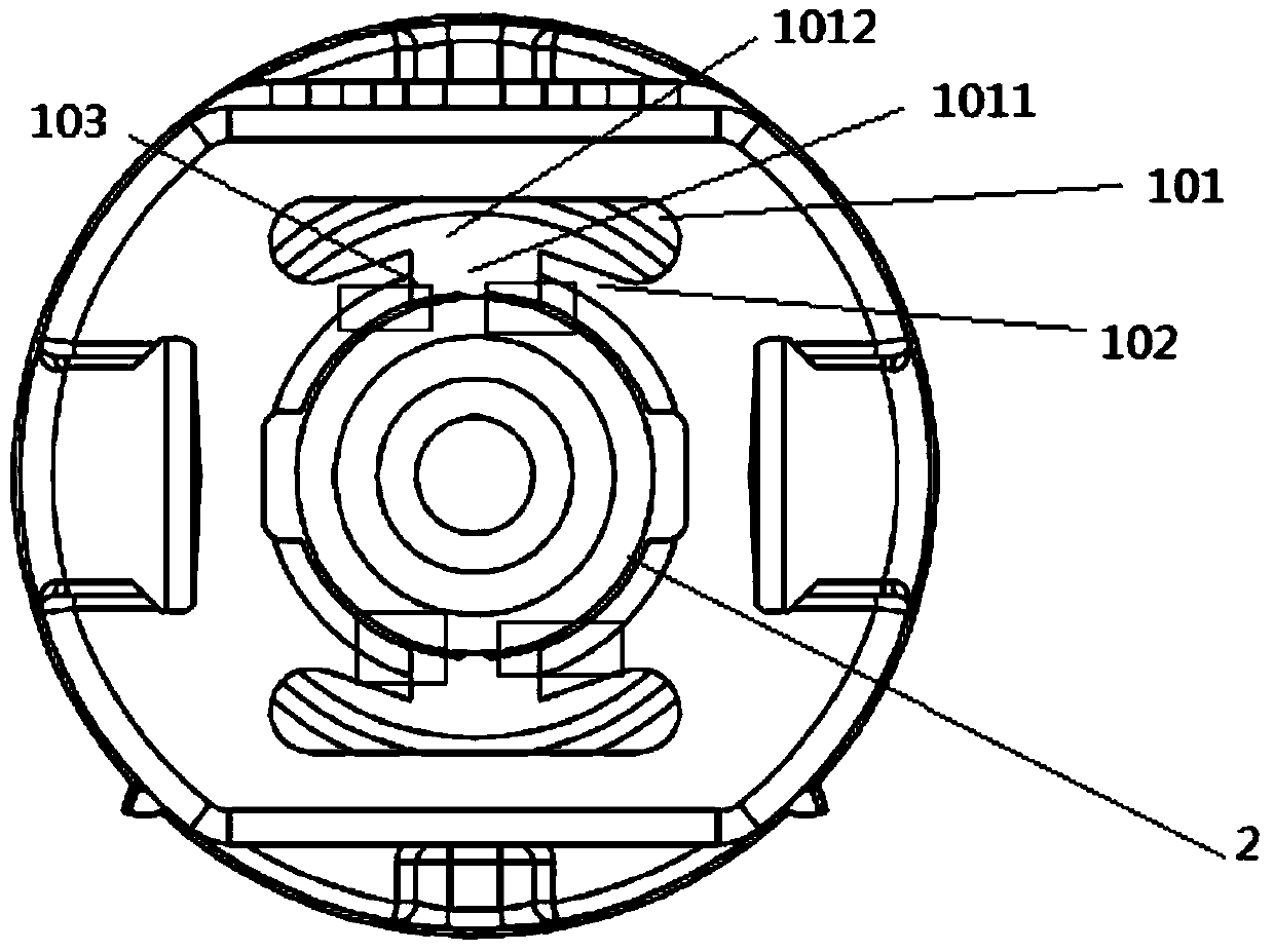
[0023] figure 1 and figure 2 The assembly of the functional assembly 10 on the shaft 2 is shown. The functional assembly 10 can comprise a holding element 1 , a functional part 3 , a holding clip 4 and an axial locking mechanism 5 . Wherein, when the functional component 10 is used as a part of a non-contact magnetic induction sensor, the functional component is a magnetic component, and the functional component 3 is a magnet, preferably a ring magnet. In this case, the holding element can have a bearing for carrying the functional component 3 . The functional part 3 carried on the holding element can be fixed on the holding element 1 by means of holding clips 4 covering the magnets. The holding element 1 can comprise a receptacle for being slipped on the shaft 2 . Along the socketing direction of socketing the holding element 1 on the shaft, the accommodating part may successively include a positioning area A and a clamping area B, through the positioning area A and the ...


PUM


Abstract

The invention provides a holding element fixed to a shaft. The holding element comprises an accommodation part connected to the shaft in a sleeving mode, and the accommodation part is sequentially provided with a locating area and a clamping area in the direction of connecting the holding element to the shaft in a sleeving mode. The holding element is characterized in that the clamping area is provided with a plurality of flexible deformable parts and the flexible deformable parts are arranged in the mode that the holding element automatically deforms towards the shaft so as to interfere with the shaft after the holding element is formed through a mold. The invention further provides a function assembly comprising the holding element. Through the simple structure, the contradiction between the clamping effect and the manufacturing process can be resolved.

Description

technical field [0001] The disclosure relates to a holding element for fastening on a shaft and to a functional assembly having the holding element. Background technique [0002] The following description of the background technology is only for illustrating the background of the present disclosure, and is by no means an acknowledgment that it belongs to the prior art. [0003] Retaining elements are often used in cases where a functional component (such as a ring magnet) needs to be securely fixed on the shaft. For example, in vehicles, it is often necessary to use non-contact magnetic induction sensors (such as Hall sensors, magnetoresistive sensors) to detect the linear position of the shaft. In this case, the ring magnet can be fixed on the circular shaft via the retaining element and moved together with the shaft. The aforementioned shaft may be the drive shaft of a servo piston or a mode valve. As the magnet moves past the sensing position of the sensor, the sensor ...

Claims


Application Information

Patent Timeline
Patent Type & Authority Patents(China)
IPC IPC(8): F16B21/16
Inventor 张冠星徐小迟B·舍曼
Owner SENSATA TECHNOLOGIES INC
Why Eureka
Try Eureka