Grain drying machine with dust-collecting device

A technology for grain dryers and dust collection devices, which is applied in the direction of dryers, drying gas arrangement, drying, etc., and can solve the problems such as the effect of dust removal effect is not obvious

Inactive Publication Date: 2017-01-18
SUNCUE
View PDF5 Cites 3 Cited by
  • Summary
  • Abstract
  • Description
  • Claims
  • Application Information

AI Technical Summary

Problems solved by technology

However, because the grains in the drying space 51 are densely stacked, only the grain dust adjacent to the air duct group 63 may be discharged

Method used


Image

  • Grain drying machine with dust-collecting device
  • Grain drying machine with dust-collecting device
  • Grain drying machine with dust-collecting device

Examples


Embodiment Construction

[0011] Embodiments of the present invention will be further described below in conjunction with the accompanying drawings.

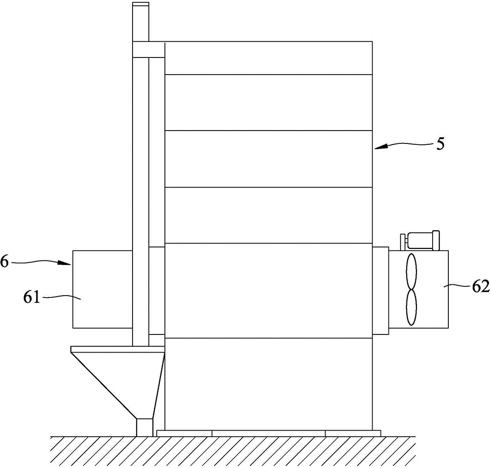
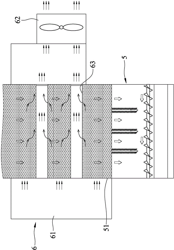
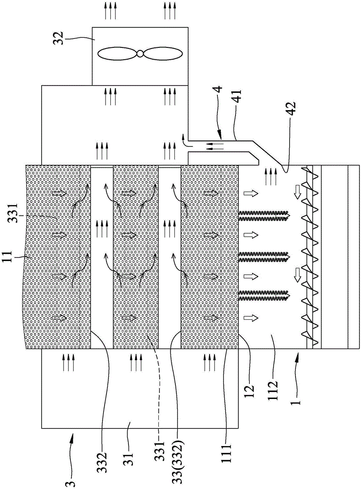
[0012] see image 3 and Figure 4 , The preferred embodiment of the grain dryer with dust collecting device of the present invention includes a casing 1, several claws 2, a hot air dust collecting unit 3, and a main dust collecting unit 4.

[0013] The casing 1 defines a hollow chamber 11 and includes a partition 12 separating the hollow chamber 11 into an upper drying space 111 and a lower grain collecting space 112 . The partition 12 has several openings 121 for the grain to fall from the drying space 111 to the grain collecting space 112 .

[0014] The several claws 2 are rotatably arranged adjacent to the opening 121 and respectively located in the drying space 111 , and can pull the grains located in the drying space 111 and drop them into the grain collecting space 112 . The flow of the grain falling into the grain collecting space 112 from the ...


PUM


Abstract

A grain drying machine with a dust-collecting device comprises a shell, a hot air dust-collecting unit and a main dust-collecting unit, wherein the shell defines a hollow accommodation chamber and comprises a partition plate used for partitioning the hollow accommodation chamber into a drying space and a grain collecting space; the partition plate is provided with a plurality of openings for grains to fall into the grain collecting space from the drying space; the hot air dust-collecting unit comprises a hot-air blower, an exhaust fan and an air flue group; the hot-air blower is arranged on one side of the shell; the exhaust fan is arranged on the other side of the shell; the air flue group communicates with the hot-air blower, the exhaust fan and the drying space; and the main dust-collecting unit comprises a dust-collecting pipe for communicating the grain collecting space with the exhaust fan. By the exhausting and absorbing force of the exhaust fan, grain dust in the hollow accommodation chamber can be discharged by the exhaust fan through the air flue group and the dust-collecting pipe.

Description

technical field [0001] The invention relates to a grain dryer, in particular to a grain dryer with a dust collecting device. Background technique [0002] see figure 1 and figure 2 , a known grain drying machine includes a casing 5 that defines a drying space 51, and a hot air device 6. The hot air device 6 includes a hot air blower 61 arranged on one side of the casing 5 , an exhaust fan 62 arranged on the other side of the casing 5 , and an air duct group 63 . The air duct group 63 is arranged in the drying space 51, and communicates with the hot air blower 61, the exhaust fan 62 and the drying space 51, and can guide the hot air generated by the hot air blower 61 to bend forward and flow into the drying space 51 to delay the drying process. The time that the hot air stays in the drying space 51 can reach the effect of fully drying the grains. The hot air device 6 needs to send the hot air to the drying space 51, and needs to discharge the hot air, so it will form a h...

Claims


Application Information

Patent Timeline
IPC IPC(8): F26B17/12F26B21/00
Inventor 林荣郎
Owner SUNCUE
Why Eureka
Try Eureka