Monitor lens positioning assembly

A technology of lens positioning and monitoring, applied in the direction of instruments, optical components, installation, etc.

Inactive Publication Date: 2017-01-18
HWAN MING ENTERPRISE
View PDF8 Cites 2 Cited by
  • Summary
  • Abstract
  • Description
  • Claims
  • Application Information

AI Technical Summary

Problems solved by technology

[0009] Therefore, in order to solve the problems of the existing positioning assembly structure, the purpose of the present invention is to provide a monitor lens positioning assembly, which includes a positioning sleeve and a locking piece; The connecting part fixed to the equipment, the front end of the connecting part extends a sleeve part, the sleeve part is in the shape of a conical rod, the sleeve part has an inclination angle, and the diameter of the sleeve part adjacent to the connecting part is larger than that away from the connecting part Diameter, the outer peripheral surface of the sleeve part forms a threaded part, and a through groove area parallel to the axial direction of the sleeve part is formed on the periphery of the sleeve part. There are at least two through groove areas, and the angle between adjacent through groove intervals is Similarly, a threaded hole that can be locked with the threaded protruding rod of the lens is provided inside the sleeve part. The through groove area runs through to the threaded hole, and the through groove area forms a clearance groove adjacent to the threaded hole; the locking member is on the outer peripheral edge The force application part is formed, and the interior of the locking piece is provided with an internal thread hole corresponding to the threaded part of the sleeve part

Method used


Image

  • Monitor lens positioning assembly
  • Monitor lens positioning assembly
  • Monitor lens positioning assembly

Examples


Embodiment Construction

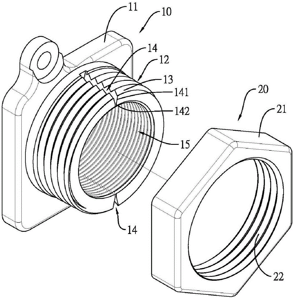
[0046] The monitor lens positioning assembly of the present invention mainly includes a positioning sleeve and a locking piece. Figure 1 to Figure 6 where is the first type of positioning component, Figure 7 Then it is the second type of positioning component.

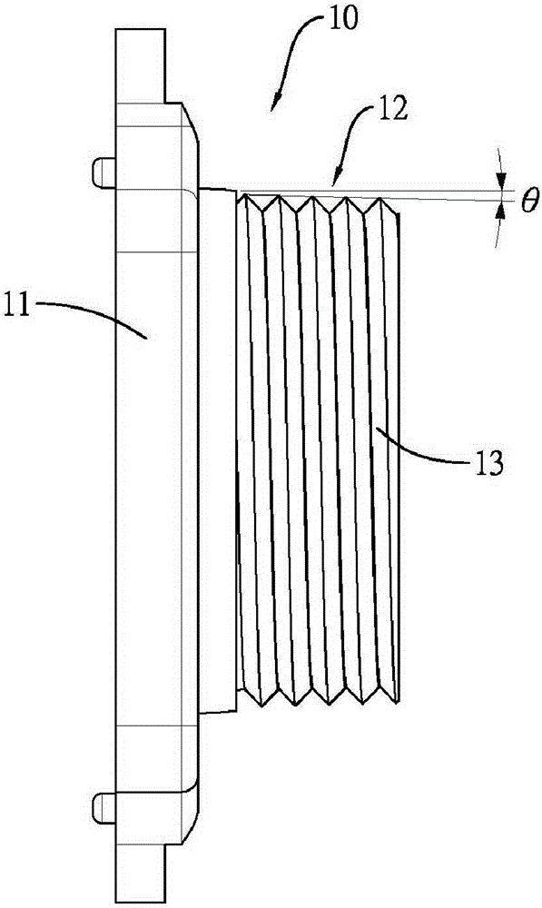
[0047] Please see first figure 1 As shown, the monitor lens positioning assembly of the present invention includes a positioning sleeve 10 and a locking member 20, wherein the positioning sleeve 10 has a connecting portion 11 fixed with the monitor main equipment, through the connecting portion 11 and the monitor main equipment Combination relationship, so that the positioning sleeve 10 is located at the front end of the monitor main equipment, and the front end of the connecting part 11 extends a sleeve part 12. The sleeve part 12 is in the shape of a conical rod. Please refer to figure 2 As shown, there is an inclination angle of θ, so that the diameter of the sleeve portion 12 adjacent to the connecting portio...


PUM


Abstract

The invention relates to a monitor lens positioning assembly. The monitor lens positioning assembly comprises a positioning sleeve and a locking member. The positioning sleeve comprises a sleeve part. At least two through trough areas which are parallel with the axial direction are formed at the peripheral edge of the sleeve part. The locking member can be locked at the sleeve part of the positioning sleeve. Then a threaded projected rod of the lens is locked in the sleeve part. Afterwards through rotating the locking member, the sleeve part can generate a clamping force which is applied in the radial direction of the threaded projected rod, thereby stably positioning the lens and preventing shakes.

Description

technical field [0001] The invention relates to a monitor lens positioning assembly, in particular to a positioning assembly applied to various monitor lenses. Background technique [0002] In the case of not involving personal privacy leaks, the setting of monitors is quite common, so as to achieve the purpose of monitoring and security. In order to make the images obtained by the monitors enough for identification, the image capture system of the monitors is more and more important. Sophisticated, the resolution of the lens is getting higher and higher to obtain better images. [0003] If you want to obtain a better image, in addition to the resolution of the lens, whether the lens is fixed in a stable position without any shaking of the imaging state must be considered, because if the lens only shifts slightly, the image quality will be affected. Acquisition has a great influence, but the existing lens positioning components all have the trouble of slightly shifting the ...

Claims


Application Information

Patent Timeline
Patent Type & Authority Applications(China)
IPC IPC(8): G02B7/02
CPCG02B7/022
Inventor 陈铭村
Owner HWAN MING ENTERPRISE
Why Eureka
Try Eureka