Eureka AIR delivers breakthrough ideas for toughest innovation challenges, trusted by R&D personnel around the world.

Fingerprint Recognition Module

A fingerprint identification and inner surface technology, applied in the direction of acquiring/organizing fingerprints/palmprints, character and pattern recognition, printing image collection, etc., can solve problems such as troubles, achieve reduced light loss, good recognition rate, and enhanced recognition rate Effect

Active Publication Date: 2019-06-25
GINGY TECH
View PDF7 Cites 0 Cited by
  • Summary
  • Abstract
  • Description
  • Claims
  • Application Information

AI Technical Summary

Problems solved by technology

In order to solve the trouble of entering passwords when traditionally unlocking and take into account the convenience and safety of electronic devices, the industry has begun to study how to install fingerprint identification modules in electronic devices to use the unique fingerprint information on human fingers for identification.

Method used


Image

  • Fingerprint Recognition Module
  • Fingerprint Recognition Module
  • Fingerprint Recognition Module

Examples


Embodiment Construction

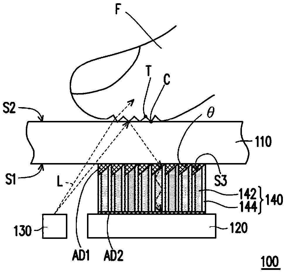
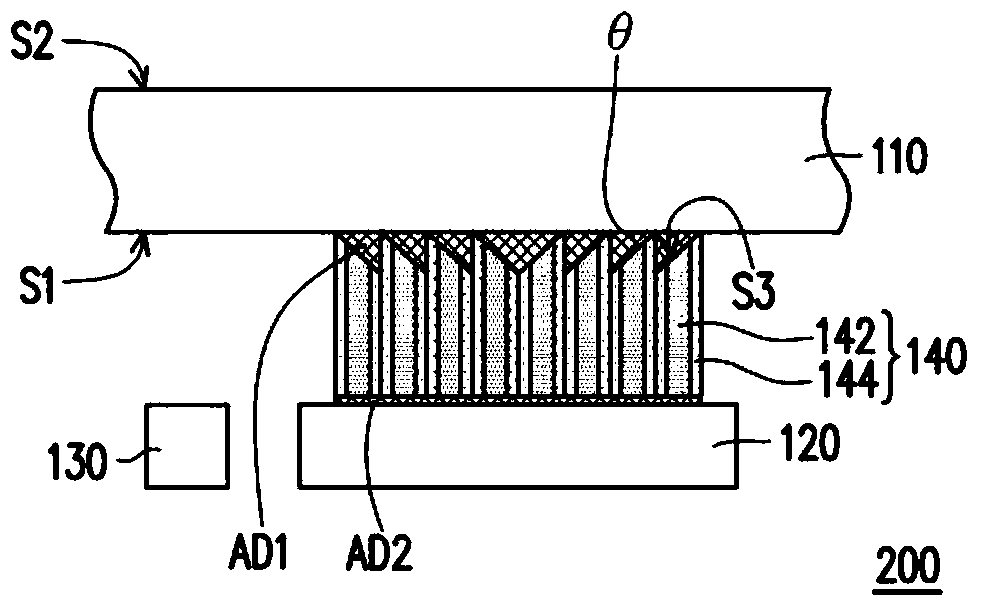
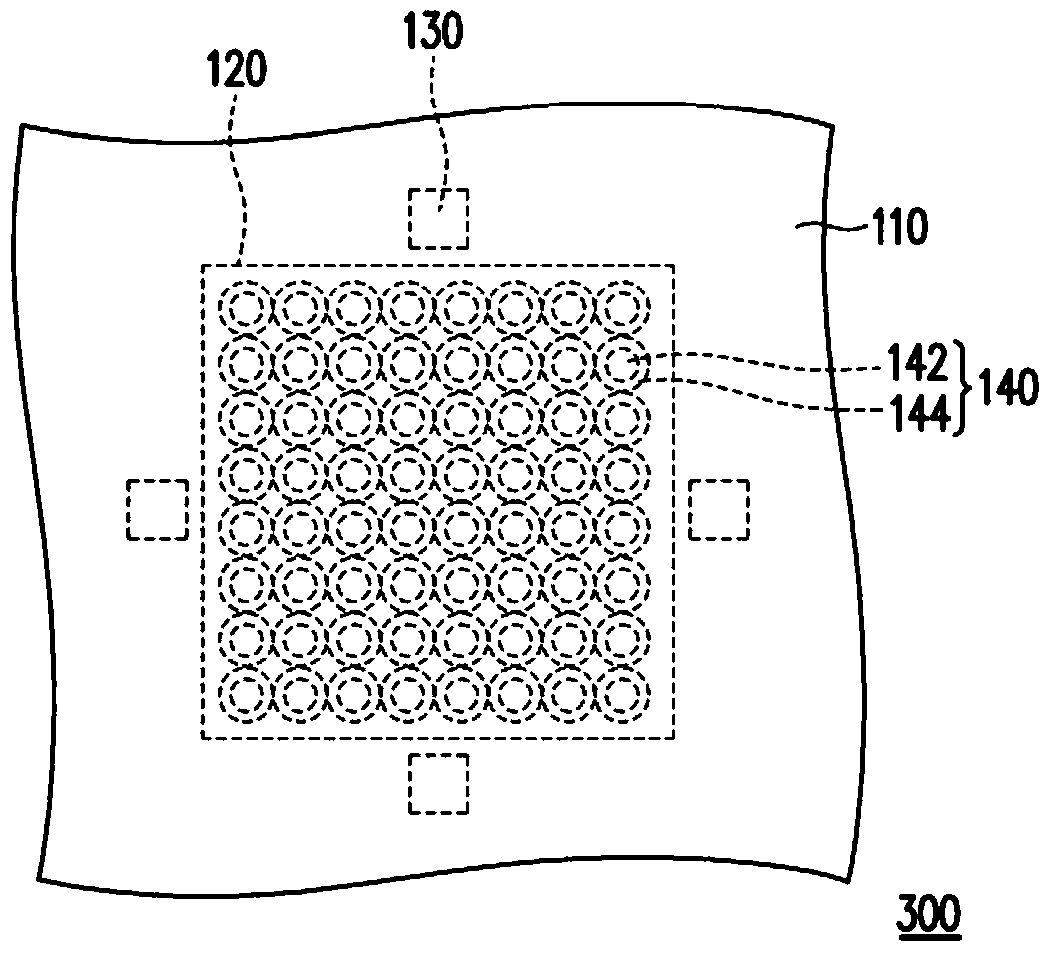
[0036] figure 1 is a schematic cross-sectional view of a fingerprint recognition module according to the first embodiment of the present invention. Please refer to figure 1 , the fingerprint recognition module 100 includes a cover plate 110 , a fingerprint reader 120 , at least one light source 130 and a plurality of optical fibers 140 . figure 1 One light source is schematically shown, but the number of light sources 130 is not limited thereto.

[0037] The cover plate 110 has an inner surface S1 and an outer surface S2 opposite to the inner surface S1. The outer surface S2 of the cover plate 110 is the touch operation surface of the fingerprint identification module 100 . In other words, the user touches the outer surface S2 of the cover 110 with his finger F for fingerprint identification. The cover plate 110 can be made of a substrate with high mechanical strength, so as to prevent components located under the cover plate 110 from being damaged by the pressing of the f...


PUM


Abstract

The invention provides a fingerprint identification module, which includes a cover plate, a fingerprint identification device, at least one light source and a plurality of optical fibers. The cover plate has an inner surface and an outer surface opposite the inner surface. The fingerprint reader and the at least one light source are located under the inner surface, and the at least one light source is located next to the fingerprint reader. The optical fibers are arranged in an array and located between the cover plate and the fingerprint reader, wherein each optical fiber has a light incident surface. The light incident surface faces the inner surface and is inclined relative to the inner surface. The fingerprint identification module provided by the present invention has a good identification rate.

Description

technical field [0001] The invention relates to an optical module, in particular to a fingerprint recognition module. Background technique [0002] With the increasing development of the technology industry, electronic devices such as tablet computers and smart phones have been widely used in daily life. These electronic devices are usually provided with coded locks to enhance the safety of use. However, in order to unlock the password lock, the user must input the password each time before using the electronic device. In order to solve the trouble of entering a password when unlocking traditionally and take into account the convenience and safety of electronic devices, the industry has begun to study how to install fingerprint identification modules in electronic devices to use the unique fingerprint information on human fingers for identification. Contents of the invention [0003] The invention provides a fingerprint recognition module with good recognition rate. [...

Claims


Application Information

Patent Timeline
Patent Type & Authority Patents(China)
IPC IPC(8): G06K9/00
CPCG06V40/1341G06V40/1324G06V40/13G06V40/1318G06V40/1365
Inventor 巫仁杰
Owner GINGY TECH
Why Eureka
Eureka Blog
Learn More