Vertical-type transformer structure

A transformer and vertical technology, which is applied in the field of vertical transformer structure, can solve the problems that the distance along the surface cannot meet the safety regulations, and the manufacturing cost is rising.

Inactive Publication Date: 2017-01-18
MEANWELL GUANGZHOU ELECTRONICS
View PDF6 Cites 10 Cited by
  • Summary
  • Abstract
  • Description
  • Claims
  • Application Information

AI Technical Summary

Problems solved by technology

[0009] (2) In addition, in the design of the transformer structure 1' in the prior art, the part where the secondary side coil 122' is drawn to the second terminal group 115' is obviously too close to the second E-shaped iron core 13a', resulting in The creepage distances of the transformer structure 1' in the existing technology cannot meet the relevant safety regulations
It ...

Method used


Image

  • Vertical-type transformer structure
  • Vertical-type transformer structure
  • Vertical-type transformer structure

Examples


Embodiment Construction

[0067] In order to describe a vertical transformer structure provided by the present invention more clearly, the preferred embodiments of the present invention will be described in detail below with reference to the drawings.

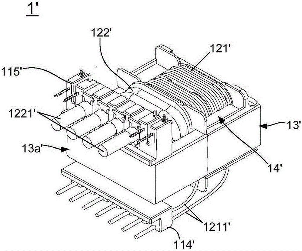
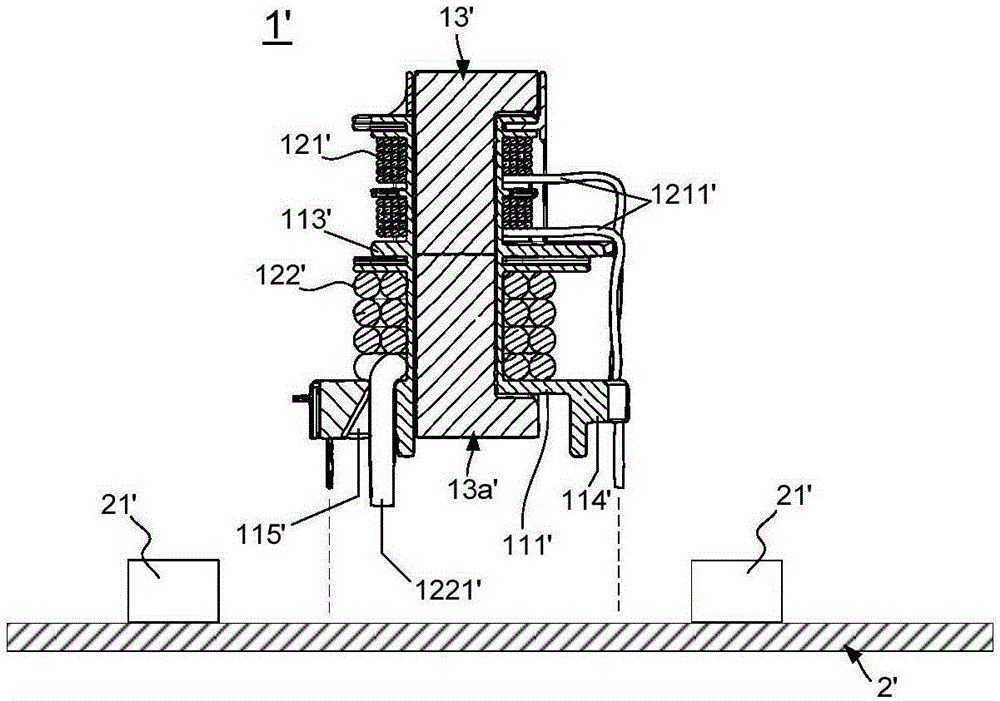
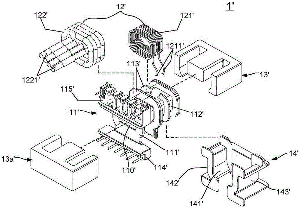
[0068] see Figure 4A and Figure 4B , Figure 4A and Figure 4B shows a perspective view of a vertical transformer structure provided by an embodiment of the present invention; and, please also refer to Figure 5A and Figure 5B , Figure 5A and Figure 5B An exploded view of the vertical transformer structure provided by the embodiment of the present invention is shown. As shown in the figure, the vertical transformer structure 1 provided by the embodiment of the present invention includes: an accommodating body 11, a first bobbin 15, a first terminal group 16, a second bobbin 17, a second terminal group 18, a first An E-shaped iron core 19 and a second E-shaped iron core 19a.

[0069] continue to refer to Figure 4A and Figure 4B as well a...


PUM


Abstract

The invention discloses a vertical-type transformer structure. The vertical-type transformer structure is different from a transformer structure in prior art. The vertical-type transformer structure is characterized in that an accommodating member is utilized for accommodating a bobbin which warps a primary-side coil. According to the vertical-type transformer structure, after a primary-side iron core is combined with the bobbin which is accommodated in the accommodating member, the accommodating member supplies effective insulation to the primary-side iron core so that a portion between the primary-side iron core and an adjacent electronic assembly can satisfy a related safety regulation. Furthermore, because the bobbin of the primary-side coil is accommodated and packaged by the central accommodating part of the accommodating member, after high voltage is input into the primary-side coil, the accommodating member supplies effective insulation to the primary-side coil, thereby preventing direct bypass of high voltage through an adjacent secondary-side iron core to the secondary-side coil.

Description

technical field [0001] The invention relates to the technical field of power electronics, in particular to a vertical transformer structure. Background technique [0002] With the evolution and development of electronic products, different electronic products need to be driven by different power supply devices; therefore, manufacturers of power supply devices are actively trying to develop various transformer structures for corresponding applications in various power supply devices . [0003] A simple transformer is composed of a first conductor and a second conductor, and when an indeterminate current passes through the first conductor, a fluctuating magnetic field is generated on the first conductor; then, based on the principle of electromagnetic mutual inductance, the fluctuation The magnetic field will cause an induced electromotive force to be generated on the second conductor, and then form a potential difference between the first conductor and the second conductor, ...

Claims


Application Information

Patent Timeline
IPC IPC(8): H01F27/32H01F27/24H01F30/06
Inventor 吴权派郑臻沣
Owner MEANWELL GUANGZHOU ELECTRONICS
Why Eureka
Try Eureka