
Hydraulic control three-jaw chuck device with function of preventing blockage of iron chips

A three-jaw chuck and functional technology, which is applied in the field of mechanical parts processing tools, can solve the problems of iron filings stuck, time-consuming, jaws stuck, etc., and achieve the effect of fast operation process, improved processing accuracy, and small labor force

Inactive Publication Date: 2017-01-25
成都欧珀琅精密工具有限公司
View PDF5 Cites 9 Cited by
  • Summary
  • Abstract
  • Description
  • Claims
  • Application Information

AI Technical Summary

Problems solved by technology

[0003] The technical problem to be solved by the present invention is that the traditional three-jaw chucks are used to clamp the workpiece manually, which has the disadvantages of time-consuming and laborious in actual work, and the traditional three-jaw chucks all use gear transmission to clamp the workpiece. There is a large gap in the structure of the claw adjustment. In the process of processing, the iron filings sometimes enter the structural gap, causing the claw to be stuck. The purpose is to provide an anti-iron The hydraulically controlled three-jaw chuck device with chip blocking function solves the problem that the three-jaw chuck is easy to enter the iron filings and get stuck and the method of gear transmission clamping is laborious.

Method used


Image

  • Hydraulic control three-jaw chuck device with function of preventing blockage of iron chips

Examples


Embodiment

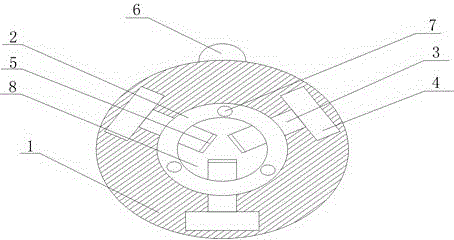
[0019] Such as figure 1 As shown, the present invention has a hydraulically controlled three-jaw chuck device with the function of preventing iron filings from clogging, comprising a disc body 1 and jaws 3, the disc body 1 is cylindrical, and a fan 6 is arranged on the outer wall of the disc body 1. The fan 6 is a miniature fan to ensure that the disk body 1 will not fall off during the rotation process. The disk body 1 is provided with a ring shaft 2, which is located at the axis of the disk body 1 and at the center of the ring shaft 2. There are through holes 8, and there are still some air outlet holes 7 on the ring shaft 2. The aperture size of the air outlet holes 7 is 0.5-0.8cm, and the air outlet holes 7 are evenly located on the surface of the ring shaft 2. The air outlet hole 7 is connected, and the duct sends the wind generated by the fan 6 to the air outlet hole 7 through the duct, and the air outlet 7 blows the wind generated by the fan 6 evenly on the surface of t...


PUM


Abstract

The invention discloses a hydraulic control three-jaw chuck device with a function of preventing the blockage of iron chips. The hydraulic control three-jaw chuck device with the function of preventing the blockage of the iron chips comprises a disc body and jack catches, wherein the disc body is provided with an annulus shaft and a fan; the center-of-circle position of the annulus shaft is provided with a through hole; the annulus shaft is also provided with a plurality of air outlet holes; the fan is connected with the air outlet holes through guiding pipes; a hydraulic mechanism is also arranged in the disc body; the hydraulic mechanism is connected with certain ends of the jack catches; the other ends of the jack catches are connected with the annulus shaft; moreover, the jack catches are located in the through hole of the annulus shaft; the jack catches are also provided with antiskid mats. According to the hydraulic control three-jaw chuck device with the function of preventing the blockage of the iron chips, a hydraulic control way is adopted to realize the clamping of the jack catches on a work piece; labor and time are saved; furthermore, by using the device, the iron chips can be effectively prevented from entering the inside of the disc body; moreover, the temperature of a surface when the work piece is machined can be also decreased; the service life of a cutter is prolonged.

Description

technical field [0001] The invention relates to a processing tool for mechanical parts, in particular to a hydraulically controlled three-jaw chuck device with the function of preventing iron filings from clogging. Background technique [0002] At present, the three-jaw chuck is an accessory tool for clamping workpieces on machine tools such as lathes and milling machines. Its function is to fix the workpiece to be processed tightly and to position the workpiece. The workpiece is clamped manually, and most of them use a series of operations such as manual fine-tuning with the pressure plate, adjustment bolts and compression bolts, which not only increases the labor intensity of the workers, but also requires a lot of force to clamp the workpiece with the three-jaw chuck. , and often the clamping is not tight enough, it is difficult to ensure uniform clamping force, and the workpiece often produces a lot of iron filings in the process of processing, the traditional three-jaw ...

Claims


Application Information

Patent Timeline
Patent Type & Authority Applications(China)
IPC IPC(8): B23B31/30
CPCB23B31/302
Inventor 钟涛赖永良候晓春
Owner 成都欧珀琅精密工具有限公司
Learn More