Cake cutting machine feeding mechanism
A technology of feeding mechanism and cake cutting machine, which is applied in metal processing and other directions, can solve problems such as low safety and inconvenient feeding operation, and achieve the effects of protecting internal parts of the body, good positioning effect, and controllable feeding speed.
- Summary
- Abstract
- Description
- Claims
- Application Information
AI Technical Summary
Problems solved by technology
Method used
Image
Examples
Embodiment 1
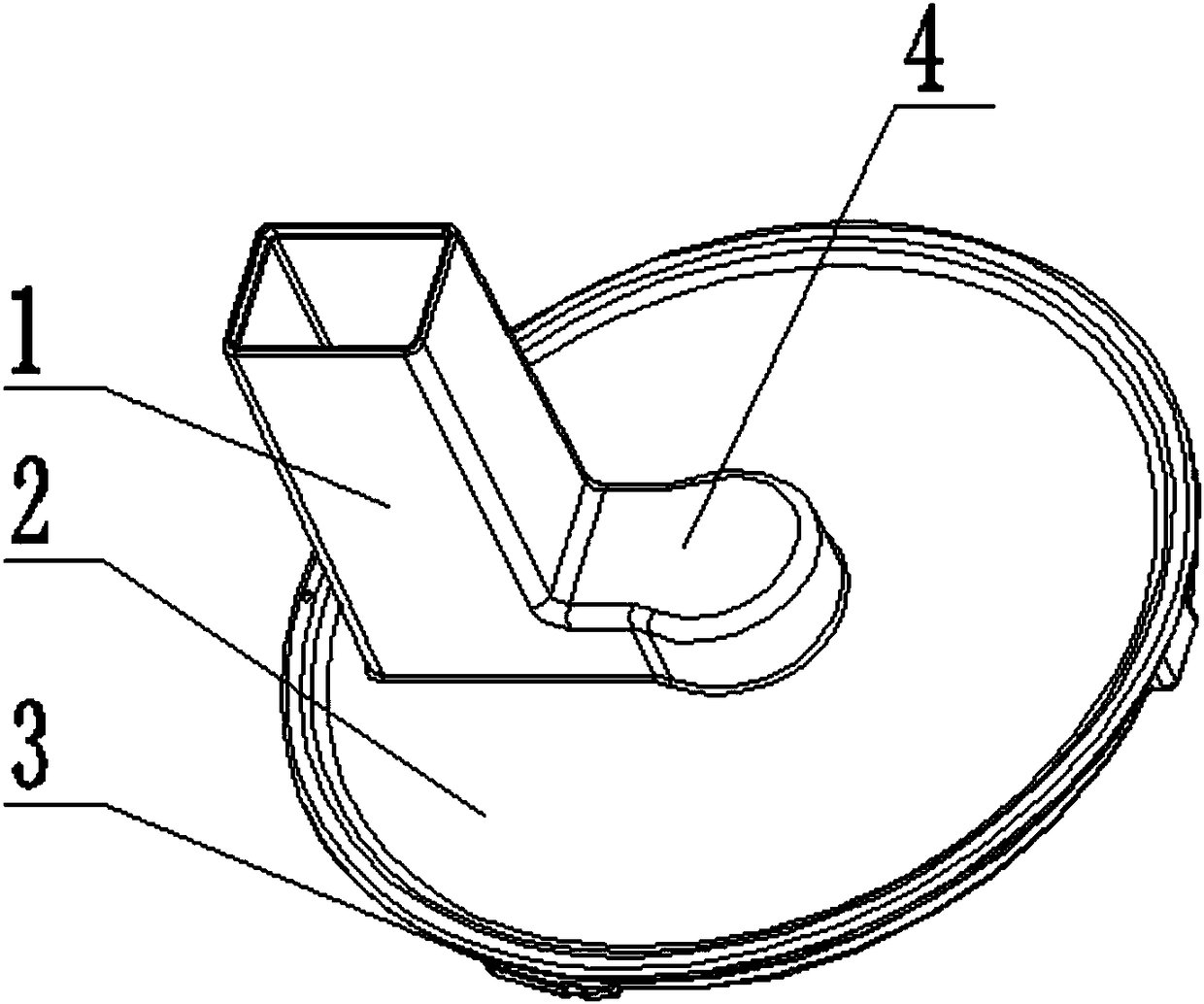
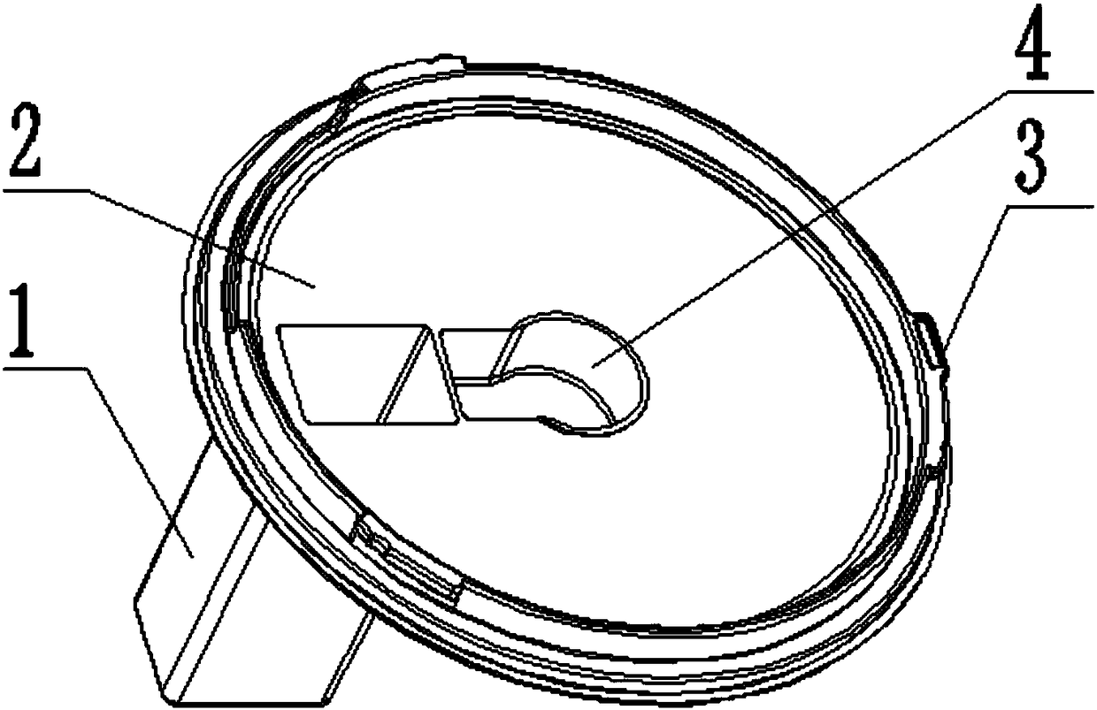
[0022] Such as figure 1 As shown, the feeding mechanism of the cake cutting machine includes a screw cap 2, a push rod 7 and a push cavity 1, the screw cap 2 is set to a disc structure, and the screw cap 2 is screwed on the upper port of the body 10 by threads, and the screw cap 2 The side wall of the lower end face of the cover 2 is ring-shaped and equidistantly provided with magnets 3, the center position of the upper end face of the screw cover 2 protrudes upwards and is provided with a cover 4, and the upper surface of the screw cover 2 close to the cover 4 is perpendicular to the screw cover 2. The material chamber 1, the material pushing chamber 1 is set as a hollow cuboid structure with through holes on the upper and lower end faces, the material pushing rod 7 is placed inside the material pushing chamber 1, and the upper end of the material pushing rod 7 is annularly provided with limiting protrusions 6 .
[0023] The cover 4 is set as an integrated structure in which ...
Embodiment 2
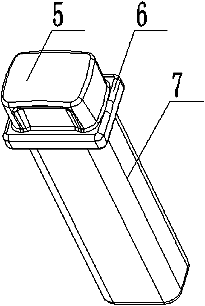
[0028] On the basis of Example 1, different from Example 1, such as image 3 As shown, the pushing rod 7 is arranged as a cuboid structure cooperating with the inner wall of the pushing chamber 1 , and the length of the lower end of the limiting protrusion 6 of the pushing rod 7 is greater than the height of the pushing chamber 1 . When the preliminarily cut donkey-hide gelatin cake bar has a large size error and cannot be dropped by its own gravity when it is placed in the feeding port of the pushing cavity 1, the function of the pushing rod 7 is to feed the donkey-hide gelatin stick in the pushing cavity 1 by manpower. A certain thrust keeps it at a normal feeding speed, which provides a guarantee for the uniformity of cutting of donkey-hide gelatin cake sticks.
[0029] The top of the pusher rod 7 is set as a pusher handle 5, and both sides of the pusher handle 5 are recessed inwardly to form a hemispherical symmetry and set as a pressing part, and the surface of the pressi...
Embodiment 3
[0031] On the basis of Example 1, different from Example 1, such as Figure 4 As shown, the bottom of the push rod 7 is provided with a detachable anti-sticking pad embedded in the thread. The anti-sticking pad is set to a hemispherical hollow elastic pad 9 with the arc facing downward, and the elastic pad 9 is arranged in a grate-shaped ring around and is provided with elastic bristles 8, the root of the elastic bristles 8 is set to a linear structure, and the tail is set to a spring structure. The elastic force of the elastic pad 9 itself and the special structure of the hemisphere, the synergistic effect of the two, under the action of the gravity and the external force of the pushing rod 7 itself, press down, and after the elastic pad 9 is pressed together, it will be pressed after the external force disappears. The pressed elastic pad 9 returns automatically under the action of elastic force; the special structure of the elastic bristles 8 can not only clean the surface o...
PUM
 Abstract
Description
Claims
Application Information
 - R&D
- Intellectual Property
- Life Sciences
- Materials
- Tech Scout
- Unparalleled Data Quality
- Higher Quality Content
- 60% Fewer Hallucinations
Browse by: Latest US Patents, China's latest patents, Technical Efficacy Thesaurus, Application Domain, Technology Topic, Popular Technical Reports.
© 2025 PatSnap. All rights reserved.Legal|Privacy policy|Modern Slavery Act Transparency Statement|Sitemap|About US| Contact US: help@patsnap.com


