Motion Control Mechanism of Mold Base and Bottom Mold of Rotary Blow Molding Machine

A technology of motion control and bottle blowing machine, which is applied in household appliances, other household appliances, household components, etc. It can solve the problems of large vibration and noise of the machine, poor synchronization and coordination accuracy, cumbersome adjustment, etc., and achieve low noise and vibration, The effect of reliability and speed improvement

Active Publication Date: 2019-04-23
广州西力机械有限公司
View PDF4 Cites 0 Cited by
  • Summary
  • Abstract
  • Description
  • Claims
  • Application Information

AI Technical Summary

Problems solved by technology

[0003] a. The synchronization and coordination accuracy between the movement of the bottom mold support and the opening and closing movement is poor;
[0004] b. When the bottom mold bracket moves up and down along the longitudinal guide rail, the machine will generate large vibration and noise;
[0005] c. It is cumbersome to adjust the movement of multiple base mold supports along the same guide rail

Method used


Image

  • Motion Control Mechanism of Mold Base and Bottom Mold of Rotary Blow Molding Machine
  • Motion Control Mechanism of Mold Base and Bottom Mold of Rotary Blow Molding Machine
  • Motion Control Mechanism of Mold Base and Bottom Mold of Rotary Blow Molding Machine

Examples


Embodiment Construction

[0023] The idea, specific structure and technical effects of the present invention will be clearly and completely described below in conjunction with the embodiments and accompanying drawings, so as to fully understand the purpose, features and effects of the present invention. Apparently, the described embodiments are only some of the embodiments of the present invention, rather than all of them. Based on the embodiments of the present invention, other embodiments obtained by those skilled in the art without creative efforts belong to The protection scope of the present invention. In addition, all the connection / connection relationships mentioned in this article do not refer to the direct connection of components, but mean that a better connection structure can be formed by adding or reducing connection accessories according to specific implementation conditions.

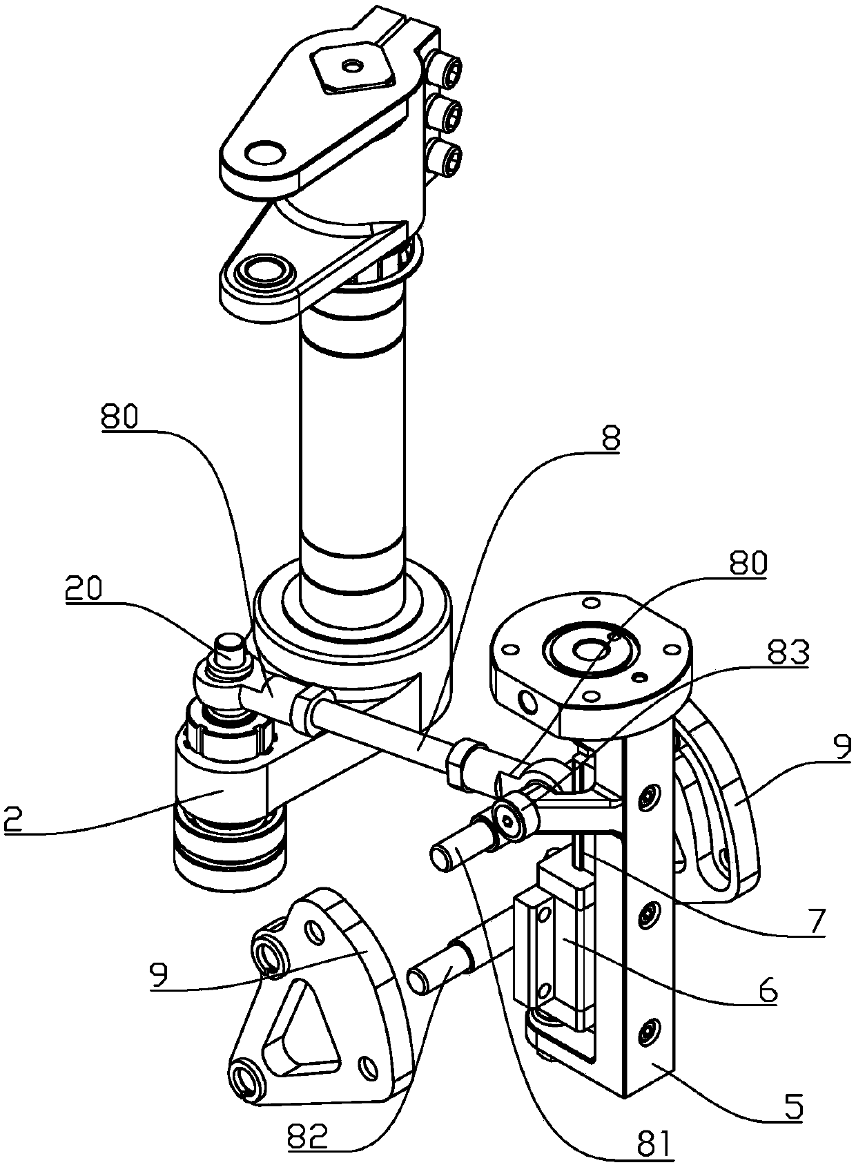
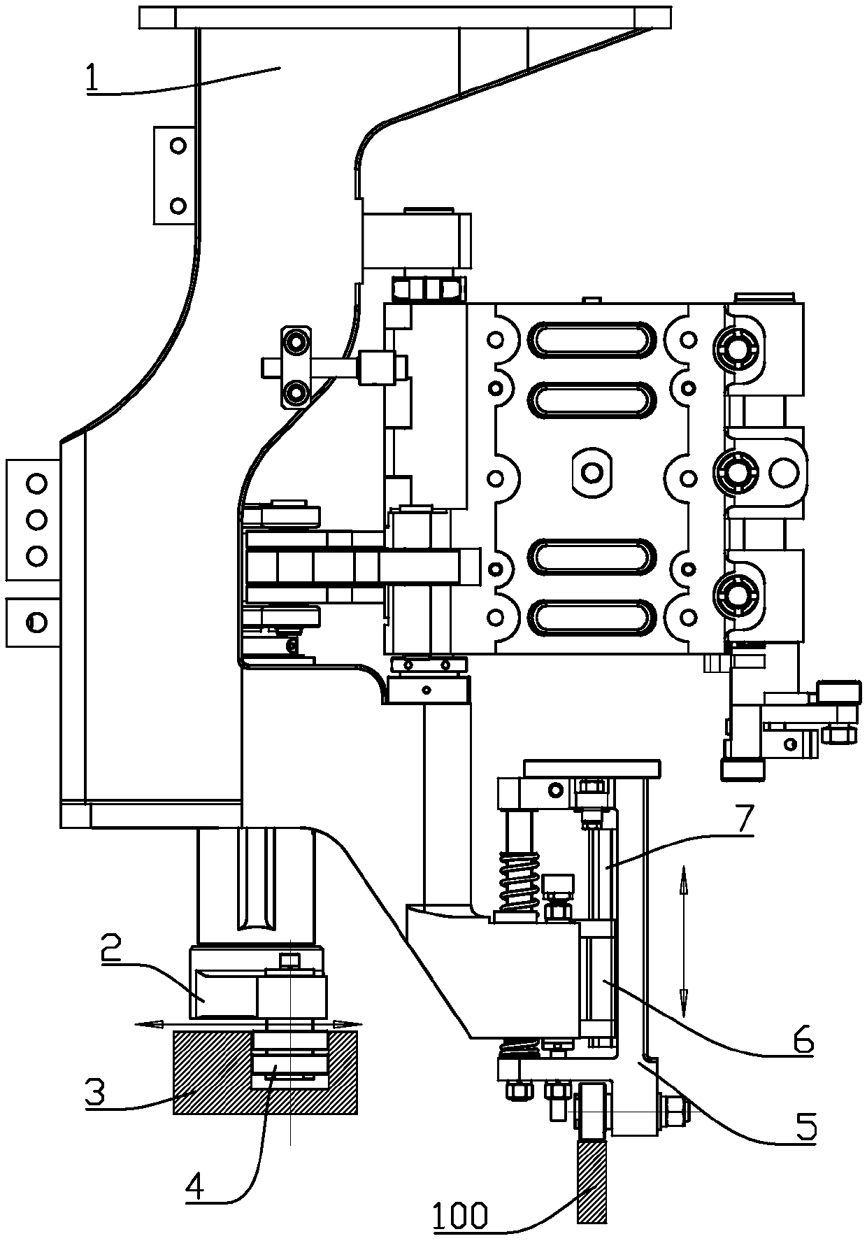
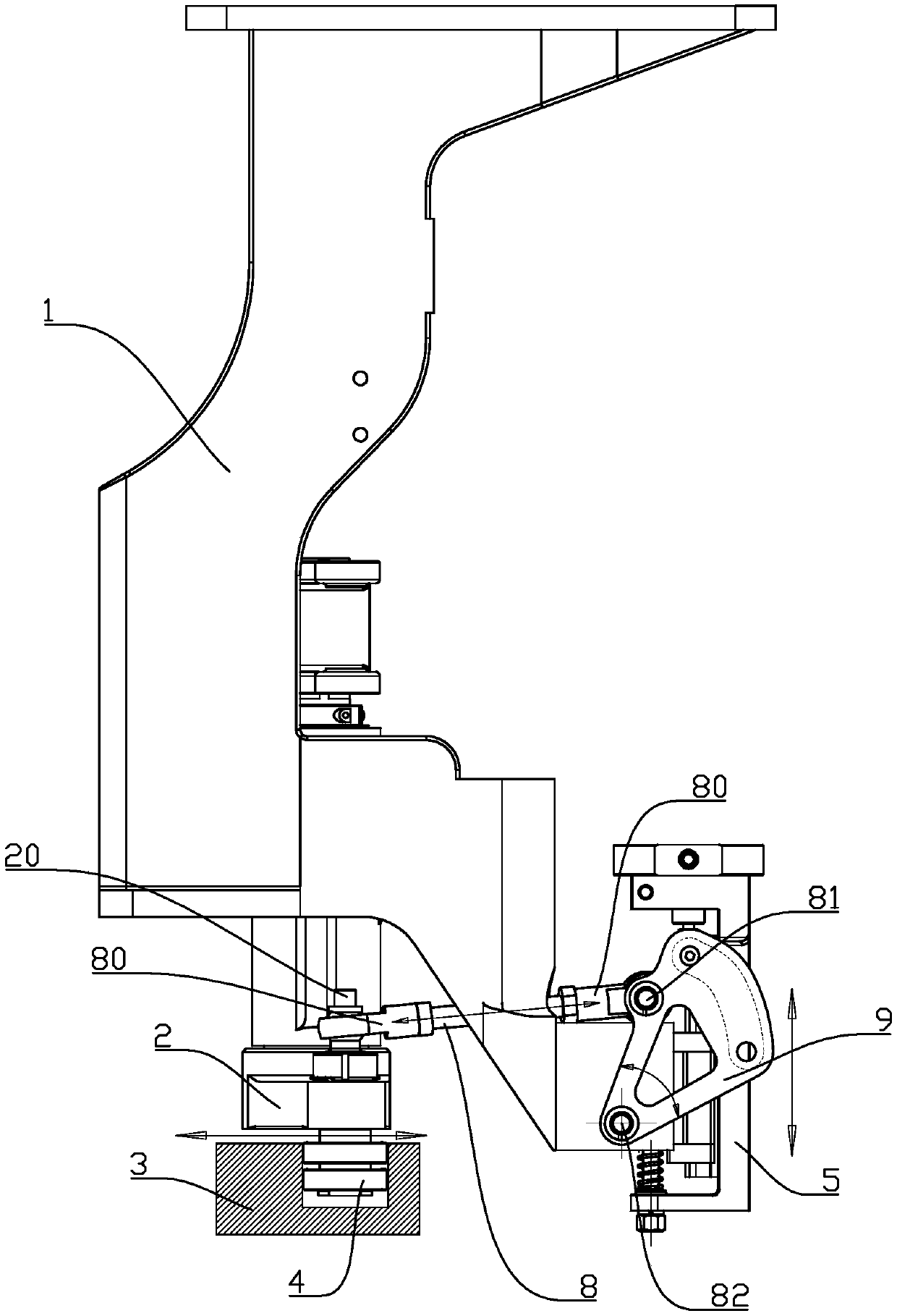
[0024] refer to Figure 2 to Figure 7 , the movement control mechanism of the bottom mold of the rotary blow mo...


PUM


Abstract

The invention discloses a bottom die movement control mechanism of a rotary bottle blowing machine die rack. The bottom die movement control mechanism comprises a die rack support, a swing arm, a horizontal guide rail and a bottom die support, wherein a crank connecting rod structure capable of driving the bottom die support to reciprocate along the vertical direction is arranged between the swing arm and the bottom die support; a ball sliding block capable of restricting the bottom die support to move along the vertical direction and a ball guide rail are arranged between the bottom die support and the die rack support. By virtue of reciprocating swing of the swing arm along the locus of the horizontal guide rail, the crank connecting rod structure drives the bottom die support to reciprocate along the vertical direction; by use of only one horizontal guide rail, the opening and closing of a forehead die rack on the die rack support and the ascending and descending of the base on the bottom die support are completely controlled, a bottom die guide rail which is traditionally used for controlling the ascending and descending of the bottom die support is omitted; under a condition of same rotation speed, the noises and vibration of the bottom die movement control mechanism are more less than those generated by a die rack when two different guide rails are respectively used for controlling respective movement of the movement bottom die and the opening and closing of the die rack in the prior art, so that a great improvement space is provided for the operation reliability and speed of machines.

Description

technical field [0001] The invention relates to a rotary bottle blowing machine, in particular to a motion control mechanism for a mold base and a bottom mold of a rotary bottle blowing machine. Background technique [0002] In the existing rotary blow molding machine, a longitudinally designed bottom mold guide rail 100 and a driving source are used to control the bottom mold support 5 to perform lifting movements, such as figure 1 shown. The existing bottom mold motion control method has the following deficiencies in practical application: [0003] a. The synchronization and coordination accuracy between the movement of the bottom mold support and the opening and closing movement is poor; [0004] b. When the bottom mold bracket moves up and down along the longitudinal guide rail, the machine will generate large vibration and noise; [0005] c. It is cumbersome to adjust the movement of multiple base mold supports along the same guide rail. Contents of the invention ...

Claims


Application Information

Patent Timeline
Patent Type & Authority Patents(China)
IPC IPC(8): B29C49/42B29L31/00
CPCB29C49/4236B29L2031/7158
Inventor 陈帮开
Owner 广州西力机械有限公司
Why Eureka
Try Eureka