
timing belt tensioner

A technology of tensioning device and synchronous belt, which is applied in the direction of belt fasteners, belt/chain/gear, mechanical equipment, etc. Tight adjustment and other problems, to achieve the effect of convenient installation and maintenance, simple structure

Active Publication Date: 2019-06-18
JIANGSU HUAZHANG LOGISTICS TECH CO LTD
View PDF7 Cites 0 Cited by
  • Summary
  • Abstract
  • Description
  • Claims
  • Application Information

AI Technical Summary

Problems solved by technology

At present, the ring-shaped synchronous belt on the hoist connects the two ends of the synchronous belt together through the connection method of the clamp block, and the clamp block and the cargo platform are fixed together, and the relative position of the two is changed by adjusting the bolts connecting the two. Then realize the tensioning of the synchronous belt. The defect of this structure is that the tensioning of the synchronous belt can only be adjusted after the clamp block is fixedly connected with the loading platform, and the tensioning of the synchronous belt cannot be performed before the synchronous belt is installed on the hoist. adjust
In addition, there is still a connection method in which the clamp block and the loading platform are welded together in the existing hoist. This connection method is inconvenient for personnel to install and maintain the equipment, and it is not convenient for the tension adjustment of the timing belt.

Method used


Image

  • timing belt tensioner
  • timing belt tensioner
  • timing belt tensioner

Examples


Embodiment Construction

[0012] In order to facilitate the understanding of those skilled in the art, the present invention will be further described below in conjunction with the embodiments and accompanying drawings, and the contents mentioned in the embodiments are not intended to limit the present invention.

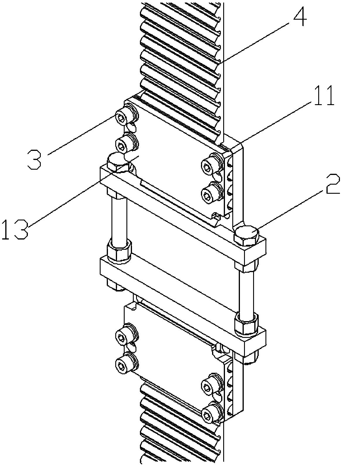
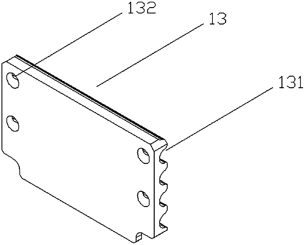
[0013] refer to Figure 1 to Figure 3 As shown, a synchronous belt tensioning device of the present invention is composed of two clamping blocks, the two are connected by bolts 2, and the distance between the two is changed by adjusting the bolts 2; the clamping blocks include: the first A splint 11 and a second splint 13;

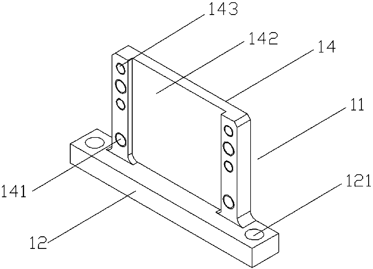
[0014] The first splint 11 is of T-shaped design, and a bolt adjusting hole 121 is respectively provided at both ends of its transverse portion 12 to accommodate the above-mentioned bolt 2; and several mounting holes 141 are respectively provided at both ends of its longitudinal portion 14 ( There are four), the first clamping block 11 is fixedly connected to the loadin...


PUM


Abstract

The invention discloses a synchronous belt tensioning device. The synchronous belt tensioning device is formed by two clamping blocks, and the two clamping blocks are connected through bolts; the clamping blocks comprise first clamping plates and second clamping plates; the first clamping plates are in T shapes, bolt adjusting holes are formed in the two ends of transverse parts of the first clamping plates and used for containing the bolts; a plurality of installing holes are formed in the two ends of longitudinal parts of the first clamping plates respectively, the first clamping plates are fixedly connected with a carrying table through the installing holes, grooves for containing a synchronous belt are formed in the middles close to the side faces of the second clamping plates, and a plurality of first connecting holes are also formed in the two ends of the side faces respectively; a plurality of tooth grooves for containing synchronous-belt racks are arranged at the portions, close to the side faces of the first clamping plates, of the second clamping plates respectively, a plurality of second connecting holes are also formed in the two ends of the second clamping plates respectively and correspond to the first connecting holes. By means of the synchronous belt tensioning device, tensioning adjusting of the synchronous belt installed behind a lifting machine can be achieved, and tensioning adjusting of the synchronous belt installed after a lifting machine can also be achieved.

Description

technical field [0001] The invention belongs to the technical field of synchronous belt connection, and specifically refers to a synchronous belt tensioning device applied to a hoist / stacker. Background technique [0002] Nowadays, logistics technology has attracted more and more attention, and warehouses play a key role in the logistics system. The hoist / stacker plays a role in the handling of goods in the entire system, which is an indispensable link in the automated warehouse and the core of the entire automated warehouse technology. [0003] The hoist / stacker is a machine component installed in the automated three-dimensional warehouse. Its main function is to lift and transport the goods to the specified height or position. The hoist / stacker drives the synchronous belt when lifting the goods. Raise and lower the loading platform. At present, the ring-shaped synchronous belt on the hoist connects the two ends of the synchronous belt together through the connection meth...

Claims


Application Information

Patent Timeline
Patent Type & Authority Patents(China)
IPC IPC(8): F16G3/08
CPCF16G3/08
Inventor 华聚良
Owner JIANGSU HUAZHANG LOGISTICS TECH CO LTD
Learn More