Centrifugal pump accelerating device and system

A technology of speed increasing device and centrifugal pump, applied in pump device, transmission device, pump and other directions, can solve the problems of high cost, large bearing box, high cost, etc., and achieve the effect of low cost and simple overall structure

Inactive Publication Date: 2017-01-25
浙江远邦流体科技有限公司
View PDF10 Cites 2 Cited by
  • Summary
  • Abstract
  • Description
  • Claims
  • Application Information

AI Technical Summary

Problems solved by technology

[0002] In the prior art, the acceleration of centrifugal pumps generally requires the help of high-speed motors, and the power span of high-speed motors is small. If the centrifugal pump is to be adjusted at different speeds, high-speed motors with different speeds are needed, and high-speed motors are expensive. , the cost is high, so it is difficult to realize the high-power span operation of the centrifugal pump by using a high-speed motor to increase the speed of the centrifugal pump
[0003] In the high-speed operation of chemical centrifugal pumps, the two-stage bearing box is usually used to achieve the speed increase. The bearing box is large in size and high in cost and maintenance. Additional oil circuits and cooling equipment are required to ensure the normal operation of the gearbox.
[0004] To sum up, the main technical problems of centrifugal pumps in the prior art are: the centrifugal pump has a small speed increase span and high cost

Method used


Image

  • Centrifugal pump accelerating device and system
  • Centrifugal pump accelerating device and system
  • Centrifugal pump accelerating device and system

Examples


Embodiment 1

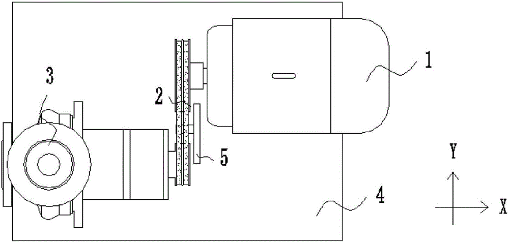
[0046] Embodiment 1 provides a speed increasing device for a centrifugal pump, which can realize a wide range of adjustment of the rotational speed of the centrifugal pump 3 under the joint action of the pulley transmission mechanism 2 and the driving mechanism 1 . Moreover, the installation of the centrifugal pump 3 and the drive mechanism 1 on different axes is realized, the installation is more flexible and convenient, and it can adapt to various working conditions.

Embodiment 2

[0047] Embodiment 2 provides a centrifugal pump speed-up system, including the centrifugal pump speed-up device and the centrifugal pump 3 provided in Embodiment 1. The centrifugal pump speed-up system can realize the centrifugal pump 3 under the action of the centrifugal pump speed-up device. Wide range of speed adjustment.

[0048]Embodiment 1 and embodiment 2 are described in detail below in conjunction with accompanying drawing:

[0049] Example 1

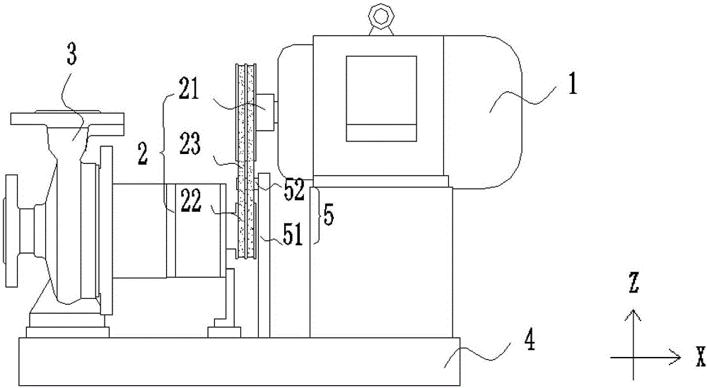
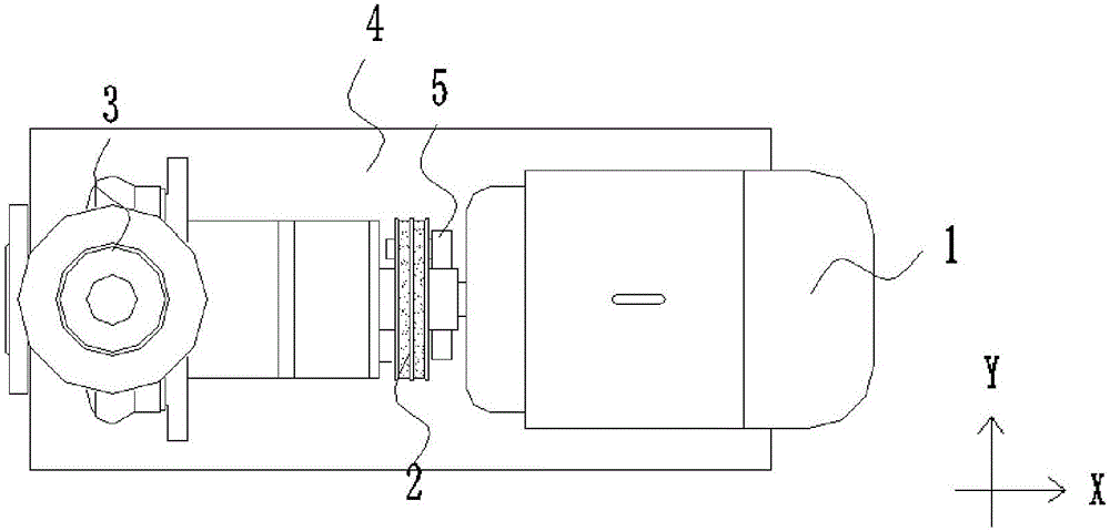
[0050] This embodiment provides a speed increasing device for a centrifugal pump, including a drive mechanism 1 and a pulley transmission mechanism 2, the centrifugal pump 3 and the drive mechanism 1 are fixed on the bottom plate 4, and the pulley transmission mechanism 2 is located between the drive mechanism 1 and the centrifugal pump 3 For connecting drive mechanism 1 and centrifugal pump 3.

[0051] The pulley transmission mechanism 2 includes a driving pulley 21 located at the end of the drive mechanism 1 and rotatably c...


PUM


Abstract

The invention relates to the technical field of centrifugal pumps, in particular to a centrifugal pump accelerating device and system to relieve the technical problem of smaller accelerating range of a centrifugal pump in the prior art. The centrifugal pump accelerating device comprises a drive mechanism and a belt pulley transmission mechanism, wherein a centrifugal pump and the drive mechanism are fixed on a bottom plate; the belt pulley transmission mechanism is located between the drive mechanism and the centrifugal pump, is used for connecting the drive mechanism and the centrifugal pump and comprises a driving belt pulley, a driven belt pulley and a transmission belt. The rotating speed of the centrifugal pump can be adjusted in a large range by controlling the transmission ratio of the driving belt pulley to the driven belt pulley and the rotating speed of the drive mechanism. The centrifugal pump accelerating device is simple in overall structure and realizes operation without an additional auxiliary device, thereby being lower in cost.

Description

technical field [0001] The invention relates to the technical field of centrifugal pumps, in particular to a centrifugal pump speed increasing device and system. Background technique [0002] In the prior art, the acceleration of centrifugal pumps generally requires the help of high-speed motors, and the power span of high-speed motors is small. If the centrifugal pump is to be adjusted at different speeds, high-speed motors with different speeds are needed, and high-speed motors are expensive. , the cost is high, so it is difficult to realize the high-power span operation of the centrifugal pump by using a high-speed motor to increase the speed of the centrifugal pump. [0003] In the high-speed operation of chemical centrifugal pumps, the two-stage bearing box is usually used to achieve the speed increase. The bearing box is large in size and high in cost and maintenance. Additional oil circuits and cooling equipment are required to ensure the normal operation of the gearb...

Claims


Application Information

Patent Timeline
Patent Type & Authority Applications(China)
IPC IPC(8): F16H7/02F16H7/12F04D13/06
CPCF16H7/02F04D13/06F16H7/023F16H7/1254
Inventor 卢鸿鹏杨安奔
Owner 浙江远邦流体科技有限公司
Why Eureka
Try Eureka