Large object plane x-ray fringe image transformation tube and electron optical imaging system

A technology for X-ray and image changing tubes, which is applied in the directions of X-ray tube electrodes, X-ray tubes, X-ray tube parts, etc. Noise immunity, effect of reducing pitch

Active Publication Date: 2019-01-04
SHENZHEN UNIV
View PDF4 Cites 0 Cited by
  • Summary
  • Abstract
  • Description
  • Claims
  • Application Information

AI Technical Summary

Problems solved by technology

But this large object plane X-ray stripe image transformation tube has the following defects: (1) the structure cathode working diameter of the existing large object surface X-ray stripe image transformation tube is small; (2) the structural characteristics make it greatly affected by field curvature, affecting The imaging performance of the system; (3) The distance between the electrodes is relatively large, and the anti-interference is poor

Method used


Image

  • Large object plane x-ray fringe image transformation tube and electron optical imaging system
  • Large object plane x-ray fringe image transformation tube and electron optical imaging system
  • Large object plane x-ray fringe image transformation tube and electron optical imaging system

Examples


Embodiment 1

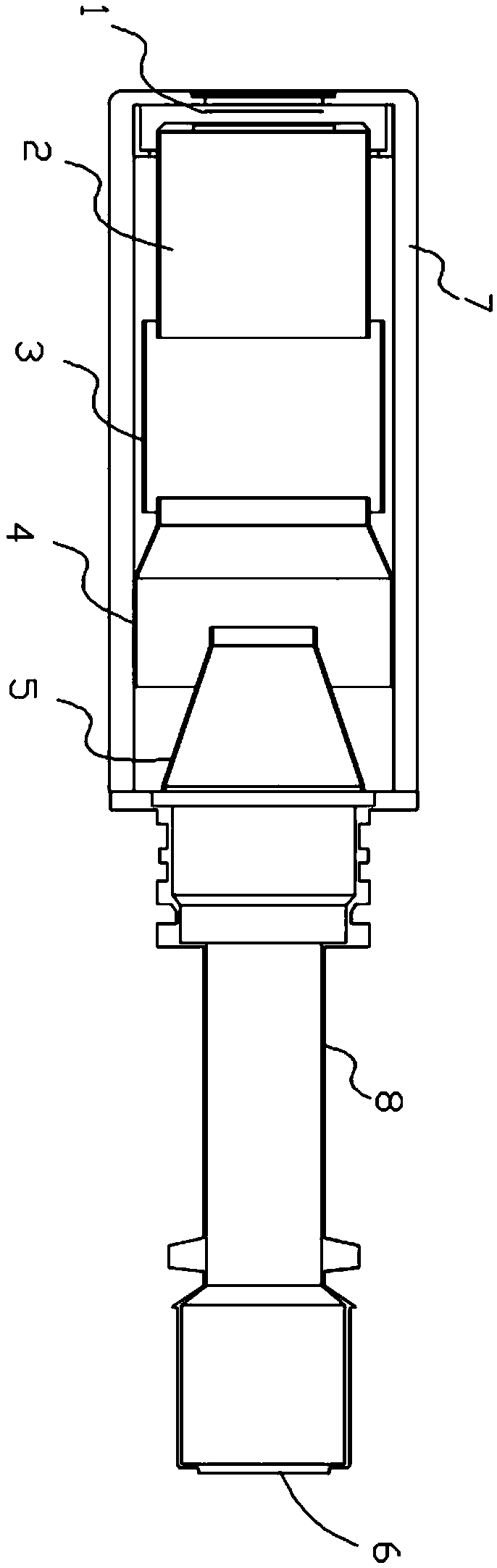
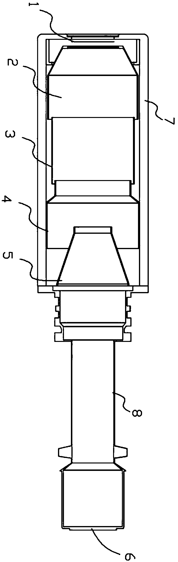
[0039] see figure 1 and figure 2 , this embodiment provides a large object plane X-ray stripe image transformation tube, including an insulating jacket 7 and a metal sleeve 8 connected to each other. The insulating jacket 7 is made of insulating material. As a preferred insulating material, the insulating jacket 7 is made of ceramics.

[0040] When the X-ray stripe image transformation tube with large object surface is working, it will generate a lot of heat. By making the material of the insulating jacket 7 be ceramic, it can not only insulate, but also play a good role in high temperature resistance. In this embodiment, the inside of the insulating jacket 7 and the metal sleeve 8 is a vacuum environment, and its vacuum degree must be lower than 0.005Pa. By drawing a vacuum, the electron beam can be kept in a vacuum, preventing ionization of the air.

[0041] A cathode 1, a grid 2, a focusing electrode assembly, and an anode 5 are arranged in sequence in the insulating ja...

Embodiment 2

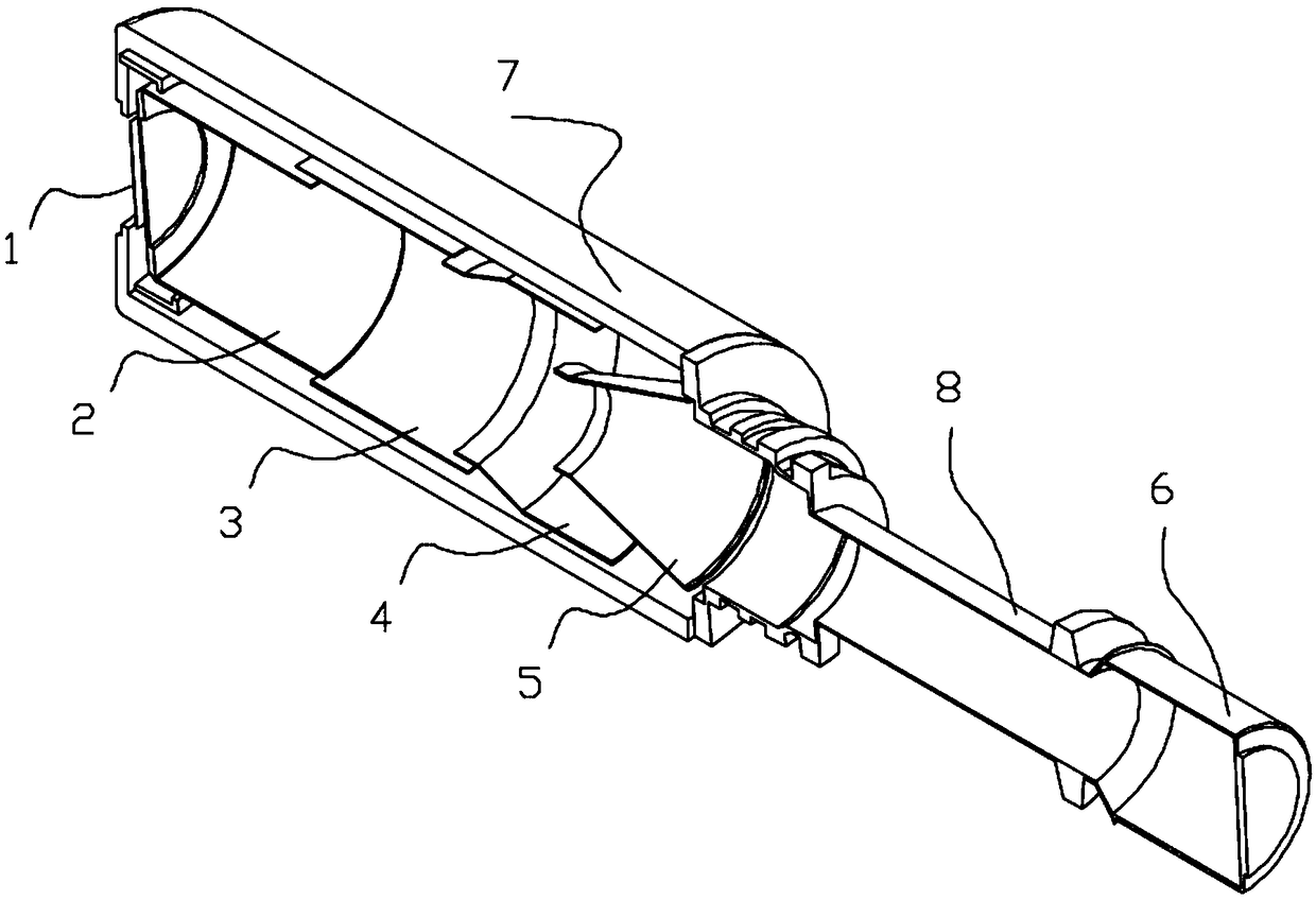
[0057] Such as image 3 , Figure 4 As shown, the present embodiment provides another large object plane X-ray stripe image transformation tube. The structure of the large object plane X-ray stripe image transformation tube in this embodiment is basically the same as that of the large object plane X-ray stripe image transformation tube in Embodiment 1. The same, the difference between the two is that this embodiment provides another grid 2, and the dimensional relationship between the grid 2 and the first focusing electrode 3, specifically as follows:

[0058] The head end of the grid 2 is a cone, the tail end of the grid 2 is a cylinder, and the first focusing electrode 3 is a cylinder. The inner diameter of the tail end of the grid 2 is larger than the outer diameter of the first focusing electrode 3, and the first focusing electrode The inner diameter of 3 is larger than the outer diameter of the first cylindrical section, the outer diameter of the first focusing pole 3 is...


PUM


Abstract

The invention provides a large object plane X-ray stripe image converter tube comprising an insulation jacket and a metal sleeve connected to each other. The insulation jacket is made of insulating material. The environment in the insulation jacket and the metal sleeve is vacuum. A cathode, a gate, a focusing electrode assembly and an anode are arranged inside the insulation jacket. The metal sleeve is arranged outside the tail of the anode. A fluorescent screen for receiving electron beams and imaging is arranged on an end part of the metal sleeve. The focusing electrode assembly comprises a plurality of focusing electrodes. The gate, the plurality of focusing electrodes and the anode generate a quasi concentric spherical electrostatic lens structure through fitting. The invention provides the large object plane X-ray stripe image converter tube with good shielding ability, strong anti-interference ability, little influence of curvature of field, and large cathode working area.

Description

technical field [0001] The invention relates to the field of electron beam imaging, in particular to a large object plane X-ray fringe image transformation tube and an electron optical imaging system. Background technique [0002] X-ray imaging technology plays an important role in medicine, safety and other fields. As the energy of inertial confinement fusion increases and the system becomes more and more complex, the cost of target shooting experiments is high. In order to improve the experimental efficiency of diagnostic systems such as streak cameras, it is required to obtain as much information as possible every time a target is shot, that is, the core component of the streak tube is required to have high temporal and spatial resolution. There are two main ways to achieve this goal: one is to improve the time-space resolution capability of the image changer tube on the basis of the existing cathode working area, and the other is to use a large working area cathode. [...

Claims


Application Information

Patent Timeline
Patent Type & Authority Patents(China)
IPC IPC(8): H01J35/04H01J35/08H01J35/14
CPCH01J35/04H01J35/045H01J35/08H01J35/14H01J2235/086
Inventor 杨勤劳张敬金
Owner SHENZHEN UNIV
Why Eureka
Try Eureka