
Image defogging method and device

An image and image representation technology, applied in the field of image processing, can solve the problem of high cost

Inactive Publication Date: 2017-01-25
HENAN UNIVERSITY OF TECHNOLOGY
View PDF3 Cites 20 Cited by
  • Summary
  • Abstract
  • Description
  • Claims
  • Application Information

AI Technical Summary

Problems solved by technology

[0004] The present invention provides an image defogging method and device, which are used to solve the problem of high cost in the process of processing foggy images in the prior art

Method used


Image

  • Image defogging method and device
  • Image defogging method and device
  • Image defogging method and device

Examples


Embodiment Construction

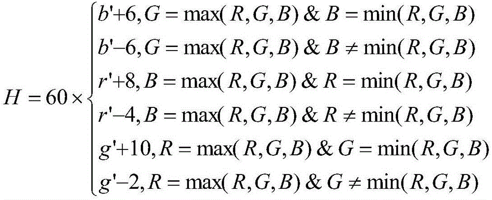
[0074] The present invention provides a method and device for defogging an image, which converts the image from the RGB color space to the HSV color space, performs defogging through filtering processing, and then converts it to the RGB color space, thereby realizing the defogging process of the image. The present invention provides The technical solution method is simple and the cost is low.

[0075] method embodiment

[0076] In this embodiment, when filtering an image, a high-pass filter is used to suppress low-frequency components and highlight high-frequency components. The traditional n-order high-pass filter transfer function is:

[0077] H ( u , v ) = 1 - e - [ D 0 D ( ...


PUM


Abstract

The invention relates to an image defogging method and device. The image defogging method comprises the steps as follows: (1) transforming a to-be-processed image from a RGB (red-green-blue) color space into an HSV (hue-saturation-value) color space; (2) extracting luminance components of the to-be-processed image; (3) performing homomorphic filtering processing on the luminance components of the to-be-processed image; (4) transforming the processed image from the HSV color space into the RGB color space; (5) outputting the processed image. The provided technical scheme has the advantages that the method is simple, requirements for hardware are not high, the cost for implementing the image defogging method is lower, and accordingly, the problem of higher cost during processing of fog images in the prior art is solved.

Description

technical field [0001] The invention relates to the technical field of image processing, in particular to an image defogging method and device. Background technique [0002] At present, many outdoor work, such as monitoring, intelligent navigation and UAV reconnaissance, are based on the monitoring or control of collected images. When there are smog or other large particles in the outdoor environment, the quality of the captured image will be reduced, and the image quality will be reduced. It is off-white, with reduced visibility, high noise, sharp attenuation of contrast and color, blurred scene outlines, and difficult image feature extraction, which eventually leads to image distortion, which greatly affects the visual effect and makes the monitoring effect worse. The intelligent navigation system may even send out Incorrect navigation instructions. [0003] Therefore, it is very important to dehaze the image to make the foggy image clear. The patent document with the pu...

Claims


Application Information

Patent Timeline
Patent Type & Authority Applications(China)
IPC IPC(8): G06T5/00
CPCG06T5/73
Inventor 梁义涛赵奎斌李亚飞李岚王锋李永刚张猛胡江汇
Owner HENAN UNIVERSITY OF TECHNOLOGY
Learn More