Parking management system for open type parking lot and management method of parking management system

A parking management and parking lot technology, applied in the open parking lot parking management system and its management field, can solve problems such as labor cost waste, low work efficiency, and personnel misoperation, and achieve labor cost saving, long service life, and wide range wide effect

Active Publication Date: 2017-01-25
INTELLIGENT INTER CONNECTION TECH CO LTD
7 Cites 18 Cited by

AI-Extracted Technical Summary

Problems solved by technology

[0005] 1. Although the simple geomagnetic parking space management system can realize the function of vehicle triggering, it still needs manual management, which may lead to misoperation of personnel, and at the same time, it is also a waste of labor costs
[0006] 2. Since the geomagnetism is buried under the parking space, and once a magnetic field disturbance occurs, the geomagnetic signal will be triggered. In practical applications...

Method used

[0092] In the foregoing Detailed Description, various features are grouped together in a single embodiment to simplify the disclosure. This method of disclosure is not to be interpreted as reflecting an intention that the embodiments of the claimed subject matter require more features than are expressly recited i...

Abstract

The invention relates to a parking management system for an open type parking lot and a management method of the parking management system. The management system comprises a camera set, a controller and a background cloud processor which are sequentially connected, wherein the camera set for acquiring vehicle information transmits acquired vehicle information to the controller, and the controller performs license plate recognition, vehicle recording and parking charging and transmits the information to the background cloud processor. With the adoption of the system, acquisition of vehicle information of the open type roadside parking lot is intelligent, an intelligent charging function of the open type roadside parking lot can be realized, the labor cost is greatly saved, and the problem of management fault possibly caused by manual misoperation is solved. Informationization of the open type roadside parking lot is realized; the vehicle information acquired by the open type roadside parking lot is finally transmitted to the background cloud processor after data processing, the information is digitized and informationized and can be provided for more systems for processing, and information sharing is effectively realized, and the acquisition view can be enlarged.

Application Domain

Technology Topic

Flight management systemManagement system +10

Image

  • Parking management system for open type parking lot and management method of parking management system
  • Parking management system for open type parking lot and management method of parking management system
  • Parking management system for open type parking lot and management method of parking management system

Examples

  • Experimental program(1)

Example Embodiment

[0059] The specific embodiments of the present invention will be further described in detail below with reference to the accompanying drawings.
[0060] The following description and drawings sufficiently illustrate specific embodiments of the invention to enable those skilled in the art to practice them. Other embodiments may include structural, logical, electrical, process, and other changes. The examples are only representative of possible variations. Unless explicitly required, individual components and functions are optional and the order of operations may vary. Portions and features of some embodiments may be included in or substituted for those of other embodiments. The scope of embodiments of the invention includes the full scope of the claims, along with all available equivalents of the claims. These embodiments of the invention may be referred to herein by the term "invention," individually or collectively, for convenience only and not to automatically limit the application if more than one invention is in fact disclosed. The scope is any single invention or inventive concept.
[0061] The invention designs a set of image-based open parking management system to charge the road test vehicle.
[0062] The system consists of a camera group, a controller, and a background cloud processor. The system collects vehicle information through the camera group, transmits the information to the controller, performs functions such as license plate recognition, vehicle recording, and parking billing, and then transmits it to the background cloud. processing module. The camera group for license plate information collection is composed of a set of high-definition network video cameras and transmission network. It is mounted on a pole to collect license plate information. The camera angle, focal length, aperture and other parameters can be adjusted freely, and one-to-one can be achieved by setting the recognition method. Or many-to-many video capture function. It has the function of transmitting video data to the controller through the network, and can also receive the control instructions sent by the controller. When the vehicle enters the recognition area of ​​the camera group, the camera starts to collect the license plate information, and uploads the video information to the controller, until the vehicle leaves the recognition area and the camera cannot capture the license plate information, it is considered that the vehicle leaves the field. The general module consists of figure 1 shown.
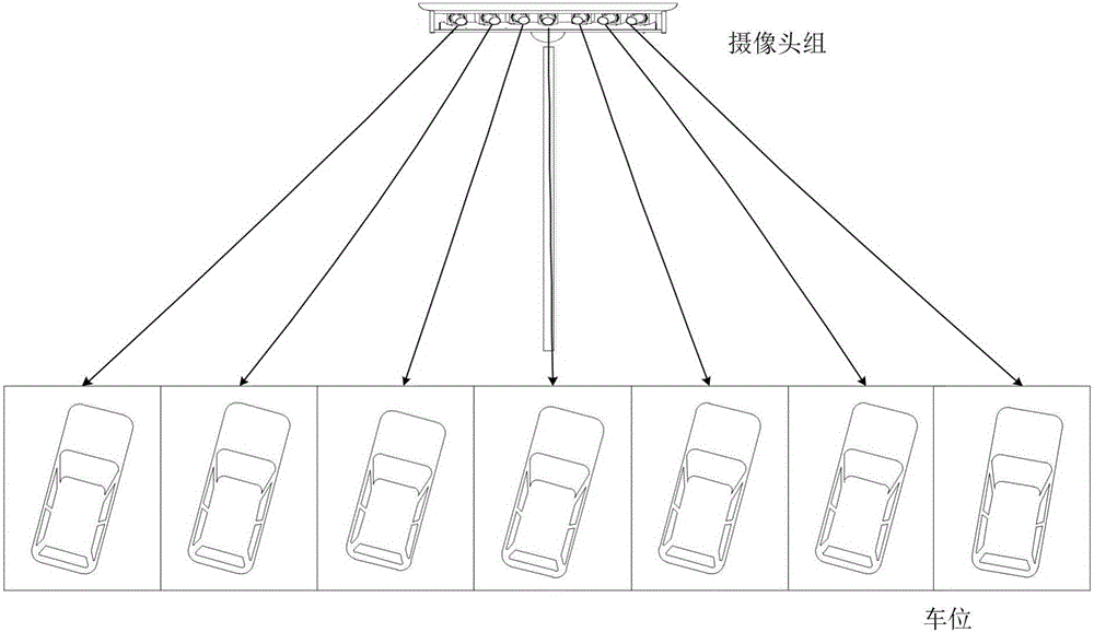
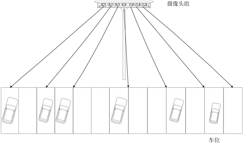
[0063] 1. The camera group consists of two parts: the video camera part and the data transmission part. The video camera part and the data transmission part are placed in a fixed shell and mounted on a pole, and the license plate recognition method is set by adjusting the camera angle and focal length, such as figure 2 , image 3 There are several identification methods.
[0064] Depend on figure 2 , image 3 As shown, the user can configure the vehicle information collection method through the control terminal to realize the function of collecting one parking space or collecting multiple parking spaces with one camera. figure 2 When the setting shown, the license plate information collection method is one-to-one collection, when the system adopts image 3 In the setting shown, the license plate information collection method is one-to-many collection. The camera group consists of multiple cameras with adjustable angle and adjustable focal length, which are respectively connected through the network.
[0065] The data transmission function is realized through the switch, and the network is connected with the camera group through the Ethernet mode. The function of this part is to transmit the vehicle information to the controller.
[0066] 2. The controller includes a data processing part and a network transmission part. The network transmission part can receive the video data returned by the camera group, and at the same time can send a series of control commands (such as snapshot, video, etc.) to the camera group, and the data processing part is responsible for correction. Image, retrieve license plate, recognize license plate.
[0067] The background cloud processor includes three parts: data processing, data storage and transmission network. The data processing performs secondary correction on the image data processed by the controller, and then retrieves it again, recognizes the license plate, performs parking billing and stores the information in the data storage. The transmission network is responsible for receiving the image data transmitted by the controller and sending control commands to the controller. An overview of the open parking management system is shown in the figure Figure 4 shown.
[0068] The present invention also provides a management method for the parking management system of an open parking lot, comprising the following steps:
[0069] The whole system workflow is as follows Figure 5 As shown, when the vehicle enters the collection range of the camera group, the camera group starts to collect vehicle information (including license plate, model, color and other information) from different angles, and the data transmission part transmits the video information to the controller through the network.
[0070] Next, the controller corrects the image, retrieves and recognizes the corrected license plate, and selects vehicles that meet the conditions set by the user (the user can set the video capture time, capture interval and other parameters), And the data is transmitted to the background cloud processor.
[0071] The background cloud processor receives the data sent by the controller, and then performs secondary correction on the image, recognizes the license plate again, and records the finally recognized vehicle information for parking billing.
[0072] When the camera group collects the license plate information for a certain period of time, the controller considers that the vehicle has left the field and ends the billing.
[0073] 1. Camera group
[0074] ①The parking lot is installed with a vertical pole, and the height can be adjusted by itself until it is moderate. The camera group is fixed in the casing, and the casing is installed on the vertical pole. The camera adopts a high-definition network camera, which can adjust the angle, focal length, aperture and other parameters at will. Users can set the method of vehicle information collection by adjusting these parameters. The camera supports the network transmission function.
[0075] ②Establish a network connection between the camera group and the switch.
[0076] ③Connect the switch to the data transmission part of the controller. The switch transmits image information to the controller, and the controller sends control commands to the camera group. (such as snapshot, timed video, etc.)
[0077] ④ When the vehicle enters the recognition area of ​​the camera group, the camera starts to collect the license plate information and upload the video information to the controller, until the vehicle leaves the recognition area and the camera cannot capture the license plate for a certain period of time, the vehicle is considered to have left the field.
[0078] 2. Controller
[0079] ① The controller consists of a data receiving part and a data processing part.
[0080] ②The controller continuously receives the image data returned by the camera group, and at the same time preprocesses images from different angles, corrects the images, and retrieves and recognizes the license plate. At the same time, the controller is responsible for sending control commands to the camera group.
[0081] ③Users can freely configure the relevant settings of data retrieval through the controller.
[0082] ④The controller judges the vehicle entering and leaving the parking lot; the judgment algorithm is divided into the license plate detection method and the trajectory tracking identification method, and the implementations are as follows:
[0083] The license plate detection method is to collect several consecutive vehicles in each parking space as the same vehicle is parked, and then judge that the identified vehicle is parked in the parking space. Similarly, when the parking space is collected several times in a row, the vehicle information does not exist or is changed to other vehicle information, it is determined that the parked vehicle has left.
[0084] The implementation of the trajectory tracking identification method is as follows. The information of the parking space and the vehicle (if there is one) in the parking space is obtained by taking pictures of the parking space at regular intervals, and then the license plate is recognized and the displacement of the license plate in the relative parking space and its relative change are identified. It is continuous movement and the position of the license plate finally enters the designated observation area. After the position of the license plate is stable, it is judged that the vehicle is parked in the parking space; when the position of the license plate moves in the observation area, the license plate cannot be detected after several times of monitoring. Or a vehicle, it is determined that the vehicle has left the parking space. If the license plate position does not move in the observation area, and the license plate or vehicle cannot be detected for several times, it is determined that the vehicle is blocked or abnormal. like Image 6 shown:
[0085] The vehicle in the parking space can drive from top to bottom (reverse entry) or from bottom to top (forward entry) in the direction of the dotted line. The shaded area is the license plate observation area. When the vehicle follows any one of ①②③ When entering the parking space, the position information of the license plate can be obtained through the front-end camera. When the license plate moves continuously and finally enters the shadow area, it can be judged that the vehicle is parked in the parking space; similarly, when the system detects that the position of the license plate changes first, After leaving the shadow area, it is judged that the vehicle has left the parking space. If the license plate position does not move and the license plate or vehicle cannot be detected, it is considered that the vehicle is blocked or abnormal.
[0086] Which judgment algorithm to use can be selected by parameter setting on the controller side.
[0087] ⑤ The controller transmits the image data and license plate information identification information to the background cloud processor, and accepts the control instructions sent back from the background.
[0088] 3. Background cloud processor
[0089] ① The background cloud processor is responsible for secondary correction of the image sent by the controller, and then secondary processing, and records the license plate recognition information and parking fee information in the cloud.
[0090] ②The background cloud processor can send control commands to the controller through the network.
[0091] Unless specifically stated otherwise, terms such as processing, computing, operating, determining, displaying, etc. may refer to the acts and/or procedures of one or more processing or computing systems, or similar systems, which acts and/or procedures would be expressed as Data of physical (eg, electronic) quantities within the processing system's registers or memory is manipulated and converted into other data similarly represented as the storage, transmission, or display of physical quantities within the processing system's memory, registers, or other such information.
[0092]In the foregoing Detailed Description, various features are grouped together in a single embodiment for the purpose of simplifying the disclosure. This method of disclosure should not be construed as reflecting an intention that embodiments of the claimed subject matter require more features than are expressly recited in each claim. Rather, as the following claims reflect, present invention lies in less than all features of a single disclosed embodiment. Thus, the following claims are hereby expressly incorporated into the Detailed Description, with each claim standing on its own as a separate preferred embodiment of this invention.
[0093] Finally, it should be noted that the above embodiments are only used to illustrate the technical solutions of the present invention and not to limit them. Although the present invention has been described in detail with reference to the above embodiments, those of ordinary skill in the art can still implement the present invention. Modifications or equivalent replacements are made in any manner, and any modifications or equivalent replacements that do not depart from the spirit and scope of the present invention are all within the protection scope of the claims of the present invention for which the application is pending.

PUM

no PUM

Description & Claims & Application Information

We can also present the details of the Description, Claims and Application information to help users get a comprehensive understanding of the technical details of the patent, such as background art, summary of invention, brief description of drawings, description of embodiments, and other original content. On the other hand, users can also determine the specific scope of protection of the technology through the list of claims; as well as understand the changes in the life cycle of the technology with the presentation of the patent timeline. Login to view more.

Similar technology patents

Method and system for automatically conveying packages, robot and storage device

ActiveCN108401423AReduce human-involved componentsReduce labor costsSortingEngineeringRobot
Owner:SHENZHEN DORABOT ROBOTICS CO LTD

Classification and recommendation of technical efficacy words

  • Good view
  • Reduce labor costs

Cloud platform for multiple account management & automated transaction processing

InactiveUS20110218849A1Good viewSuppression of theftPoint-of-sale network systemsCommerceClient-sideTransaction processing system
Owner:RUTIGLIANO JOHN R +5

Forklift truck

ActiveCN102689856AGood viewAccurate loading and unloading of goodsLifting devicesTractor-trailer combinationsVehicle frameEngineering
Owner:FUJIAN FUDA MACHINERY

Pneumoperitoneum-free peritoneoscope abdominal wall suspension device

InactiveCN103829979AGood hanging effectGood viewCannulasSurgical instrument supportLaparoscopic surgeryEngineering
Owner:JIANGSU BLUE AREA INNOVATION TECH INVESTMENT

Thin-skin ultralight recreational vehicle body system

InactiveUS7000978B1Elimination of bonding processReduce labor costsVehicle seatsSuperstructure subunitsExtremely lightVehicle frame
Owner:MESSANO FR
Why Eureka
Try Eureka