Display substrate, production method and display equipment
A technology for display substrates and functional films, which is used in semiconductor/solid-state device manufacturing, electrical solid-state devices, organic light-emitting device structures, etc., and can solve problems such as peeling and fracture, water and oxygen erosion of OLED display devices, and reducing frame sealants.
- Summary
- Abstract
- Description
- Claims
- Application Information
AI Technical Summary
Problems solved by technology
Method used
Image

Examples
Embodiment 1
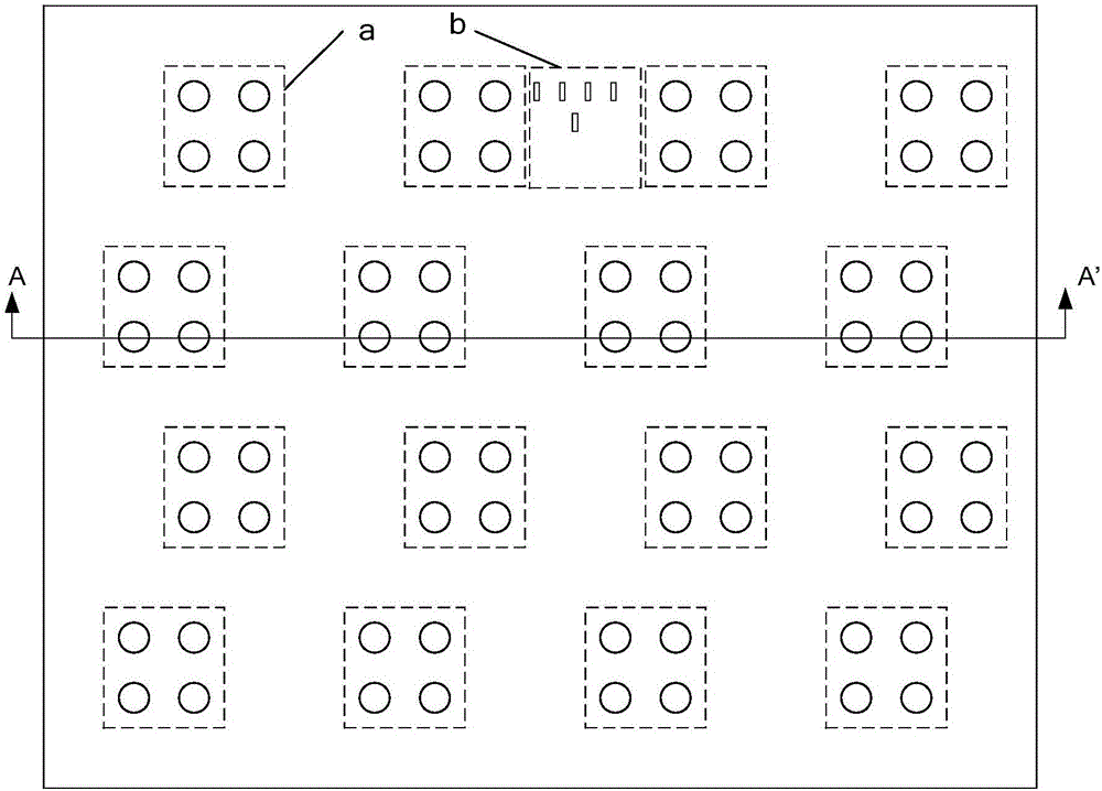
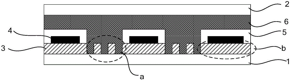
[0082] Embodiment 1. The embodiment of the present invention provides a display substrate, such as image 3 , 4 As shown, the display substrate 10 is provided with a functional film layer, and the side away from the display substrate 10 of at least one functional film layer includes a protrusion array 4010, wherein, when the display substrate 10 is boxed with another display substrate 20, the protrusion array 4010 The protrusions corresponding to the array 4010 are used to embed the sealant 50 between the display substrate 10 and another display substrate 20 .
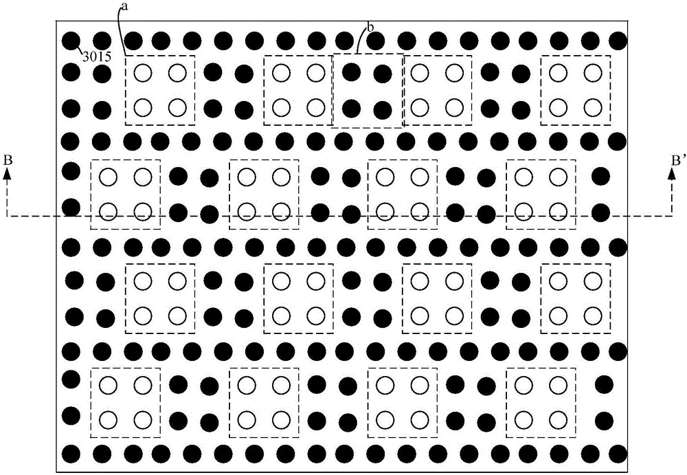
[0083] It can be seen from the above that, according to the image 3 A section in the B-B' direction can be obtained Figure 4 The specific plan perspective structure schematic diagram of the display substrate shown, where as Figure 4 As shown, by providing a functional film layer on the display substrate, at least one functional film layer includes a protrusion array on the side away from the display substrate, an...
Embodiment 2
[0084] Embodiment 2. A display substrate, such as image 3 , Figure 4 with Image 6 As shown, wherein: the protrusion array 4010 is formed by the arrangement of protrusion sub-arrays; each protrusion sub-array includes a flat portion 4011 and at least one protrusion portion 4014 disposed on the flat portion.
[0085] Specifically, the functional film layer includes a first functional film layer 30 and a second functional film layer 40; one side of the first functional film layer 30 is in contact with the display substrate 10, and the second functional film layer 40 One side of the first functional film layer 30 is in contact with the other side; the second functional film layer 40 includes the protrusion array 4010; on the second functional film layer 40 away from the display substrate 10 A protruding array 4010 is formed on one side; wherein, the flat portion 4011 and at least one protruding portion 4014 disposed on the flat portion 4011 are located on the first functional...
Embodiment 3
[0101] Embodiment 3. A display substrate, such as image 3 , Figure 5 with Image 6 As shown, wherein: the protrusion array 4010 is formed by the arrangement of protrusion sub-arrays; each protrusion sub-array includes a flat portion 4011 and at least one protrusion portion 4014 disposed on the flat portion.
[0102] Specifically, the functional film layer includes a first functional film layer 30 and a second functional film layer 40; one side of the first functional film layer 30 is in contact with the display substrate 10, and the second functional film layer 40 One side of the first functional film layer 30 is in contact with the other side; the second functional film layer 40 includes the protrusion array 4010; on the second functional film layer 40 away from the display substrate 10 A protruding array 4010 is formed on one side; wherein, the flat portion 4011 and at least one protruding portion 4014 disposed on the flat portion 4011 are located on the first functional...
PUM
 Abstract
Description
Claims
Application Information
 - R&D
- Intellectual Property
- Life Sciences
- Materials
- Tech Scout
- Unparalleled Data Quality
- Higher Quality Content
- 60% Fewer Hallucinations
Browse by: Latest US Patents, China's latest patents, Technical Efficacy Thesaurus, Application Domain, Technology Topic, Popular Technical Reports.
© 2025 PatSnap. All rights reserved.Legal|Privacy policy|Modern Slavery Act Transparency Statement|Sitemap|About US| Contact US: help@patsnap.com