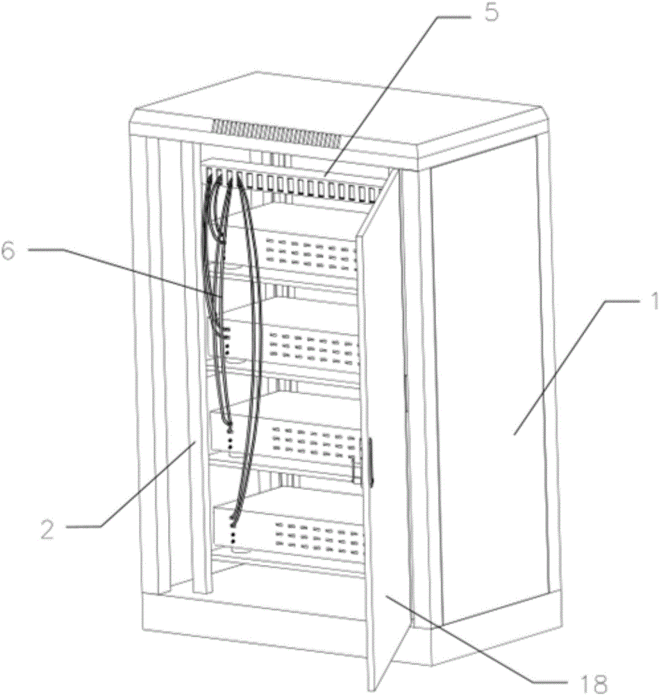
Vertical distribution frame and cabinet with vertical distribution frame
A distribution frame and frame technology, which is applied in the direction of casing/cabinet/drawer parts, electrical equipment casing/cabinet/drawer, electrical components, etc., which can solve unfavorable maintenance work, excessive occupation of cabinet space, maintenance Management chaos and other issues, to achieve the effect of saving management and maintenance costs, reducing overall construction costs, and improving aesthetics
- Summary
- Abstract
- Description
- Claims
- Application Information
AI Technical Summary
Problems solved by technology
Method used
Image
Examples
Embodiment 1
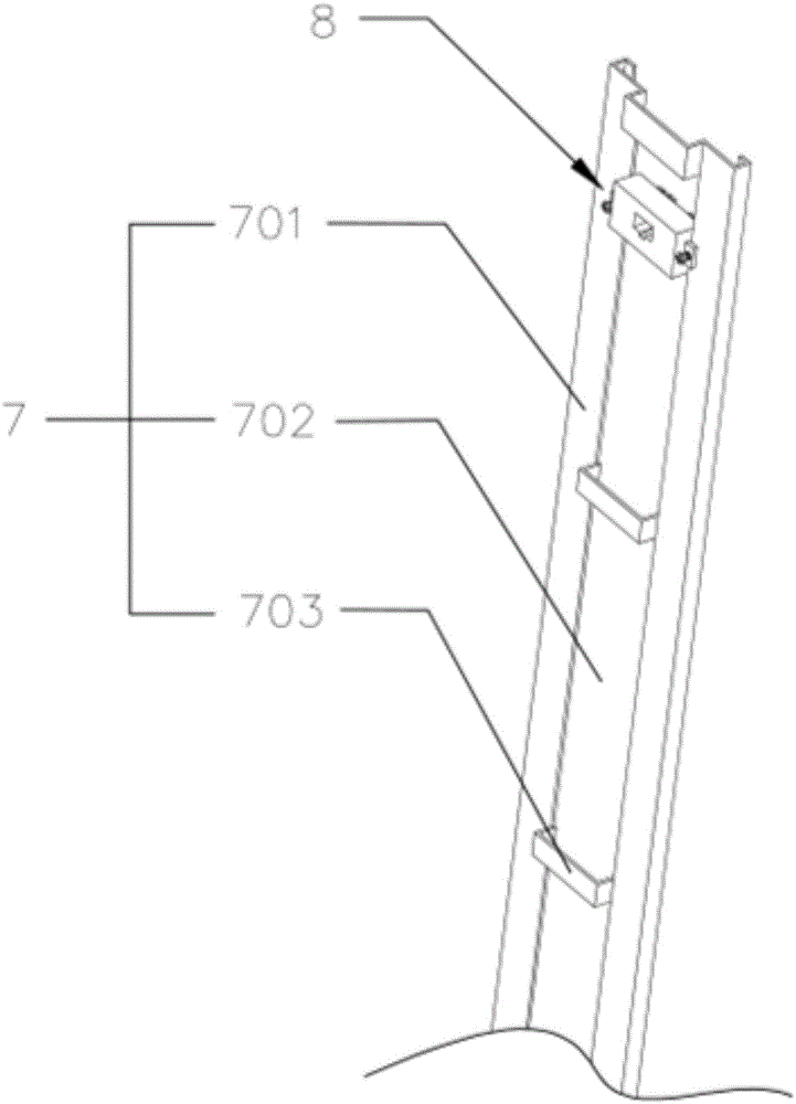
[0036] refer to figure 2 , a vertical distribution frame, including a frame body 7 and a wiring module 8, the frame body 7 includes a strip-shaped skeleton 701 and a plurality of installation grooves 702 uniformly distributed on the frame body 7 along the length direction of the skeleton 701, the installation grooves 702 runs through the frame 701 , and two adjacent mounting grooves 702 are separated by a partition 703 on the frame 701 . The wiring module 8 is installed in the installation groove 702 . Only one mounting groove 702 can also be provided, and in this case, its length is roughly equivalent to that of the skeleton 701 .
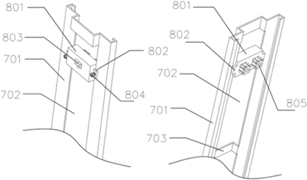
[0037] refer to image 3 The front and rear sides of the wiring module 8 protrude from the skeleton 701, and the front and rear sides of the wiring module 8 outside the skeleton 701 are respectively provided with limit blocks 802, and the front and rear two limit blocks on the same side of the wiring module 8 A space is left between 802, and t...
Embodiment 2
[0039] refer to Figure 4, a vertical distribution frame, a vertical distribution frame, including a frame body 7 and a wiring module 8, the frame body 7 includes a strip-shaped skeleton 701 and multiple wires evenly distributed on the frame body 7 along the length direction of the skeleton 701 There are two installation slots 702, the installation slots 702 run through the frame 701, and the two adjacent installation slots 702 are separated by the partition bar 703 on the frame 701. The wiring module 8 is installed in the installation groove 702 . Only one mounting groove 702 can also be provided, and in this case, its length is roughly equivalent to that of the skeleton 701 .
[0040] refer to Figure 5 The frame 701 is located at the two side edges of the installation groove 702 as a fixed bar protruding forward, and a card slot 12 is opened on the fixed bar, and a groove 9 is opened on the side of the main body 801 of the wiring module 8, and the groove Inside 9 is a br...
Embodiment 3
[0045] refer to Image 6 , a vertical distribution frame, including a frame body 7, a module frame 13 and a wiring module 8. The frame body 7 includes a strip-shaped skeleton 701 and a plurality of installation grooves 702 evenly distributed on the frame body 7 along the length direction of the skeleton 701. The installation grooves 702 run through the skeleton 701. Partition column 703 separates. The module frame 13 is located in the installation slot 702 . Only one mounting groove 702 can also be provided, and in this case, its length is roughly equivalent to that of the skeleton 701 . The parts of the frame 701 located at the two side edges of the mounting groove 702 are fixed bars protruding forward, and a plurality of evenly distributed card slots 12 are opened on the fixed bar along its length direction, and the side of the module frame 13 is provided with The card block 11 matched with the card slot 12 , the card block 11 extends into the card slot 12 to lock the mod...
PUM
 Abstract
Description
Claims
Application Information
 - R&D
- Intellectual Property
- Life Sciences
- Materials
- Tech Scout
- Unparalleled Data Quality
- Higher Quality Content
- 60% Fewer Hallucinations
Browse by: Latest US Patents, China's latest patents, Technical Efficacy Thesaurus, Application Domain, Technology Topic, Popular Technical Reports.
© 2025 PatSnap. All rights reserved.Legal|Privacy policy|Modern Slavery Act Transparency Statement|Sitemap|About US| Contact US: help@patsnap.com


