Converter device and converter device manufacturing method

A manufacturing method and converter technology, applied to electrical components, sealed enclosures, electrical equipment enclosures/cabinets/drawers, etc., can solve problems such as difficulties in miniaturization

Active Publication Date: 2017-01-25
TDK CORPARATION
View PDF7 Cites 3 Cited by
  • Summary
  • Abstract
  • Description
  • Claims
  • Application Information

AI Technical Summary

Problems solved by technology

Therefore, in the conventional electronic circuit device, there is more useless space in the area on the side of the opening than in the wiring board inside the case, and accordingly, miniaturization becomes difficult.

Method used


Image

  • Converter device and converter device manufacturing method
  • Converter device and converter device manufacturing method
  • Converter device and converter device manufacturing method

Examples


Embodiment Construction

[0033] Hereinafter, embodiments of an inverter device and a method of manufacturing the inverter device (hereinafter also simply referred to as "manufacturing method") will be described with reference to the drawings.

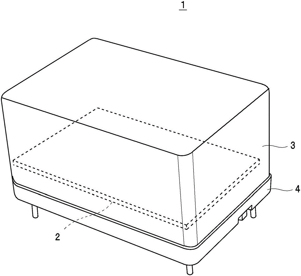
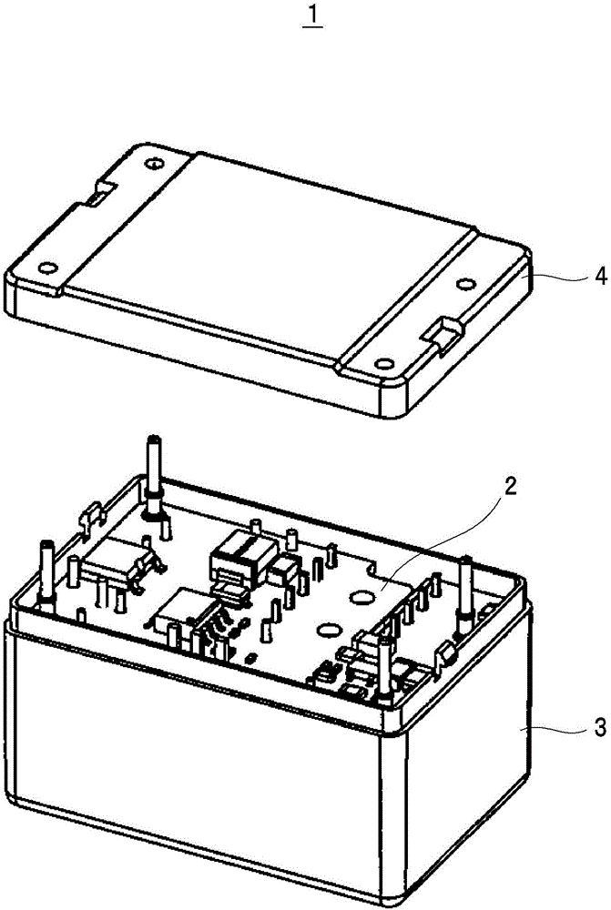
[0034] First, as an example of a converter device figure 1The structure of the shown converter device 1 is explained as follows. The converter device 1 is, for example, an AC-DC converter that inputs an alternating current and outputs a direct current, such as figure 1 as well as figure 2 As shown, it is constituted by including a mounting substrate 2 , a frame body 3 , and a cover portion 4 . In addition, in this converter device 1, as Figure 10 As shown, the filler 5 is filled in the frame body 3 .

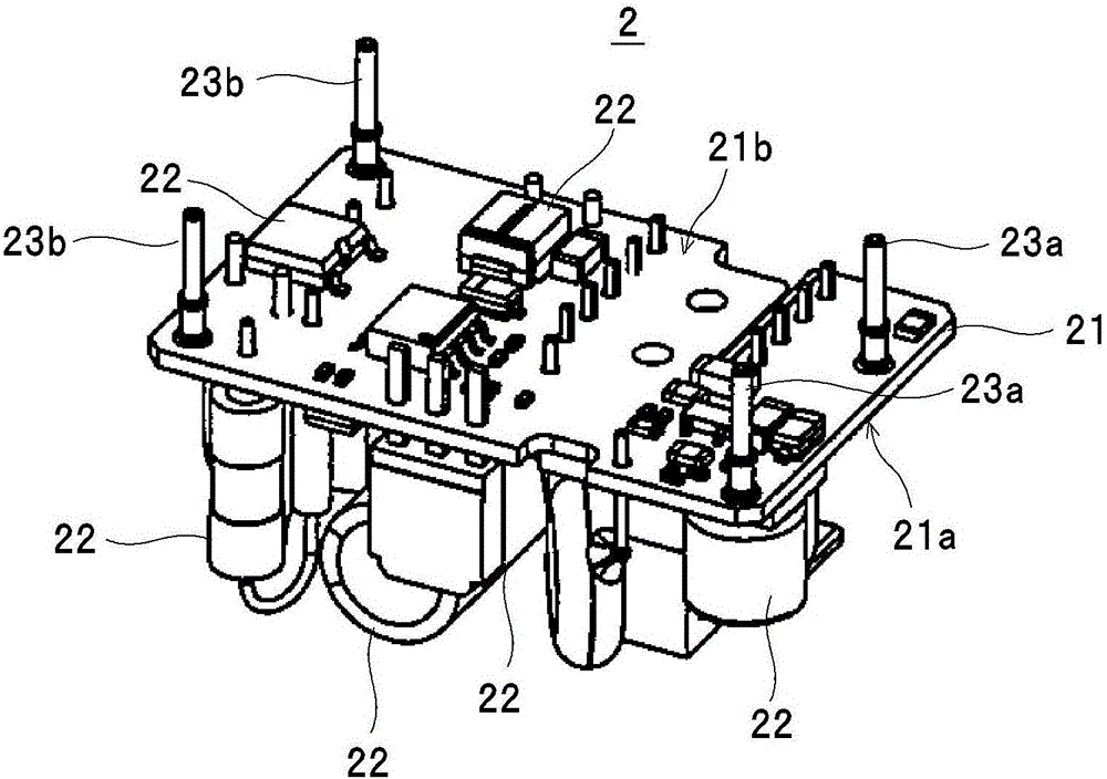
[0035] Mount substrate 2 as image 3 As shown, it is constituted by including a substrate 21 and various electrical components 22 mounted on the substrate 21 . The substrate 21 is formed in a substantially rectangular shape (for example, a substantially r...


PUM


Abstract

The invention provides a converter device and a converter device manufacturing method for reliably filling a gap between electrical components of a mounting substrate and realizing miniaturization. The converter device is provided with a mounting board (2) for mounting the base plate (3), and a cover (4) for holding the housing (3) in the form of an opening (33) and four side plates erected on the outer peripheral portions of the bottom plate (31), and the ribs (34) are formed in the form of a member (22) in the form of a member mounting panel (21a) for mounting the electric component opposed to the bottom plate and the mounting surface is abutted against the rib, and the filler is filled in the bottom plate (31) and the mounting surface (21a). The cover portion is attached to the housing in a state where the protrusion (43) provided on the inner surface abuts against the back surface of the mounting board and presses the mounting substrate against the bottom plate side.

Description

technical field [0001] The present invention relates to a converter device that includes a mounting board, a frame for accommodating the mounting board, and a cover that covers the opening of the frame and fills a filler in the frame as an electrical component covering the mounting board, and its manufacture. A converter device manufacturing method of the converter device. Background technique [0002] As such a device, a resin-molded electronic circuit device (hereinafter also referred to as "electronic circuit device") disclosed in Patent Document 1 below is known. This electronic circuit device is constituted by including a case, a wiring board on which components are mounted, and a cover-like frame covering an opening of the case. In addition, in this electronic circuit device, a filling resin is filled in the case in the form of a member covering the wiring board accommodated in the case. [0003] prior art literature [0004] patent documents [0005] Patent Docume...

Claims


Application Information

Patent Timeline
Patent Type & Authority Applications(China)
IPC IPC(8): H05K5/06
CPCH05K5/064
Inventor 北谷一治浦田光
Owner TDK CORPARATION
Why Eureka
Try Eureka