Powder remover

A technology of de-powdering and stripping, applied in beehives, applications, beekeeping, etc., can solve the problems of crowding and crowding, affecting the normal entry and exit efficiency of bees, etc., and achieve the effect of improving efficiency.

Active Publication Date: 2019-09-24
吴晓彬
View PDF7 Cites 2 Cited by
  • Summary
  • Abstract
  • Description
  • Claims
  • Application Information

AI Technical Summary

Problems solved by technology

[0005] The purpose of the present invention is to provide a depowder device to solve the problem that the bees entering and leaving the hive are crowded at the partitions during the use of the existing depowder device, which affects the normal entry and exit efficiency of the bees, so as to ensure that the bees enter and exit from different channels. Improve pollen collection efficiency

Method used


Image

  • Powder remover
  • Powder remover
  • Powder remover

Examples


Embodiment 1

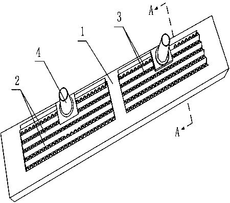
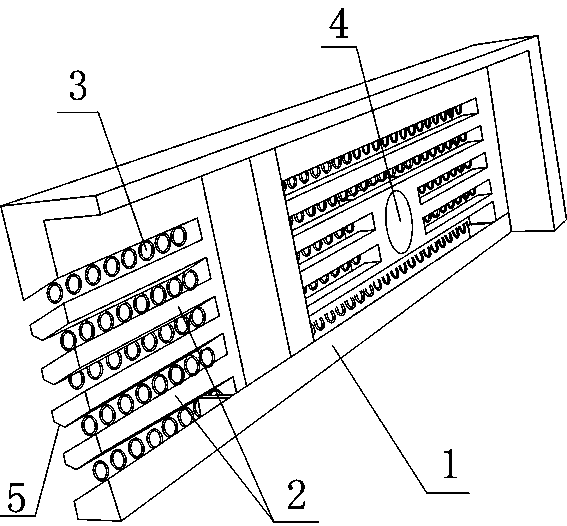
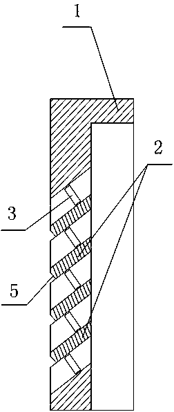
[0026] Such as Figure 1 to Figure 3 As shown, the powder remover of the present invention includes a powder remover plate body 1, and a plurality of spacers 2 are arranged in the powder remover plate body 1, and between the powder remover plate body 1 and the spacer bars 2, and adjacent Powder removal holes 3 are arranged between the spacers 2, and a one-way channel 4 is provided on the powder remover plate body 1, and the spacer bars 2 are arranged from the outside to the inside of the powder remover plate body 1, and are arranged obliquely from bottom to top; Between two adjacent spacers 2, the top edge of the spacer 2 located below is higher than the bottom edge of the spacer 2 located above. The angle between the spacer 2 and the horizontal plane is 30°. The one-way channel 4 has a smooth outer surface. On the outer side of the spacer 2 , a slope 5 that is not parallel to the outer side is cut; the powder removal hole 3 is perpendicular to the surface of the spacer 2 . ...

Embodiment 2

[0029] On the basis of Embodiment 1, the included angle between the spacer 2 and the horizontal plane in this embodiment is 60°. Good results can also be obtained.

Embodiment 3

[0031] On the basis of Embodiment 1, the included angle between the spacer 2 and the horizontal plane in this embodiment is 45°. An included angle of 45° is the optimal solution. This angle can ensure that the spacer 2 blocks light, and at the same time, it can satisfy pollen sliding down the surface of the spacer 2 and prevent pollen from staying on the spacer 2 .


PUM


Abstract

The invention discloses a pollen removing device which comprises a pollen removing plate body. multiple partition strips are arranged in the pollen removing plate body, pollen removing holes are formed between the pollen removing plate body and the partition strips and between every two adjacent partition strips, one-way channel is formed in the pollen removing plate body, and the partition strips are obliquely arrakjnged from the outer side to the inner side of the pollen removing plate body and from bottom to top. The top edge, between every two adjacent partition strips, of each partition strip located at the lower portion is higher the bottom edge of each partition strip located at the upper portion. By providing the pollen removing device, the problem that bees going in or out of a honeycomb crowd and flock together at the partition strips and normal in-out efficiency of the bees is influenced in the using process of an existing pollen removing device is solved, and it is ensured that the bees go in and out of different channels and pollen collecting efficiency is improved.

Description

technical field [0001] The invention relates to a powder remover for a bee breeding box, in particular to a powder remover. Background technique [0002] Pollen is a high-value natural nutrient, which has been widely used in catering, cosmetics and other industries. At present, collecting pollen is when honeybee enters hive box, is provided with the entrance hole of suitable size, makes honeybee be de-pollinated when passing through entrance hole, promptly the pollen collected on body is squeezed when honeybee enters into nest hole. [0003] In the prior art, Wu Xiaobin applied on May 20, 2013 for an invention patent titled "a bee powder remover", and its authorized announcement number is: CN 103270977 B. This patent is the most advanced technical solution at present, and the technical problem to be solved by this invention patent is: "During the use of the powder remover, some bees fly in circles near the one-way passage and cause confusion." The technical scheme describe...

Claims


Application Information

Patent Timeline
Patent Type & Authority Patents(China)
IPC IPC(8): A01K47/06
Inventor 吴晓彬
Owner 吴晓彬
Why Eureka
Try Eureka