Steel strip winding machine with muff-coupling limiting function

A winding machine, functional technology, applied in the field of steel strip winding machine, can solve problems such as detachment, strong tension steel strip, etc.

Active Publication Date: 2017-02-01
江苏中康金属材料有限公司
View PDF6 Cites 2 Cited by
  • Summary
  • Abstract
  • Description
  • Claims
  • Application Information

AI Technical Summary

Problems solved by technology

[0004] The purpose of the present invention is to provide a steel strip winder with a socket-limiting function, which has the advantage that the steel strip can limit the range of motion of the steel strip when it is retracted and extracted after the steel strip is sleeved on the sleeve. Solved the problem that the steel strip would be detached from the sleeve due to the strong pulling force on the steel strip when the reel was drawing the steel strip

Method used


Image

  • Steel strip winding machine with muff-coupling limiting function
  • Steel strip winding machine with muff-coupling limiting function
  • Steel strip winding machine with muff-coupling limiting function

Examples


Embodiment Construction

[0020] The following will clearly and completely describe the technical solutions in the embodiments of the present invention with reference to the accompanying drawings in the embodiments of the present invention. Obviously, the described embodiments are only some, not all, embodiments of the present invention. Based on the embodiments of the present invention, all other embodiments obtained by persons of ordinary skill in the art without making creative efforts belong to the protection scope of the present invention.

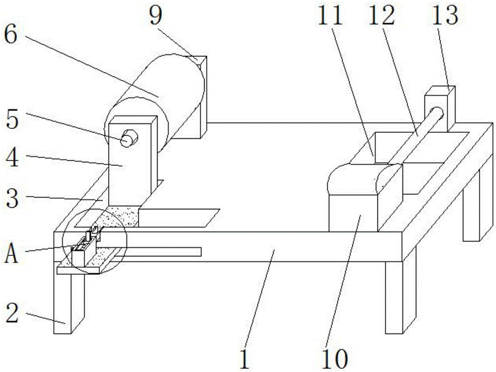
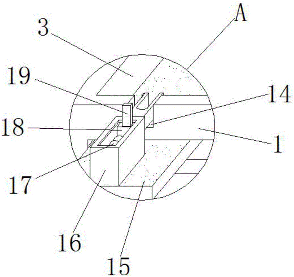
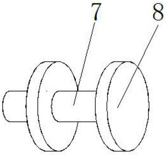
[0021] see Figure 1-5 , a steel strip coiling machine with a socket limit function, including a base 1, the bottom of the base 1 is provided with supporting legs 2, since the number of supporting legs 2 is four, and the four supporting legs 2 are respectively located on the base 1 The four corners of the bottom, so that the base 1 is more stable in contact with the ground, the left front end of the upper surface of the base 1 is provided with an L-shaped mova...


PUM


Abstract

The invention discloses a steel strip winding machine with a muff-coupling limiting function. The steel strip winding machine comprises a base. An L-shaped movable groove is formed in the left front end of the upper surface of the base. A movable plate is arranged in an inner cavity of the L-shaped movable groove. The rear end of the upper surface of the movable plate is fixedly connected with the bottom of a fixed plate. One end of a first supporting shaft penetrates through the top of the front side of the fixed plate. The other end of the first supporting shaft is fixedly connected with the axis of the front side of a sleeve. The left rear end of the upper surface of the base is fixedly connected with the bottom of a fixing device. According to the steel strip winding machine with the muff-coupling limiting function, the movable plate is pulled and moved to the other end in the inner cavity of the L-shaped movable groove; the sleeve is sleeved with a steel strip; the movable plate is moved to the original position, so that the first supporting shaft is sleeved with a through hole in the fixed plate, the movement range of the steel strip can be limited in the process of winding and pulling the steel strip after the steel strip is arranged on the sleeve in a sleeved mode, and the situation that the steel strip breaks away from the sleeve due to strong tensile force of a reel to the steel strip in the winding process when the steel strip is pulled through the reel cannot occur.

Description

technical field [0001] The invention relates to the technical field of a steel strip production line, in particular to a steel strip winder with the function of socketing and limiting. Background technique [0002] The receiving part of the coil processing production line, the raw materials are mechanically wound into coils, which are widely used in paper rolls, cloth rolls, and metal coil processing production lines. The design is diversified according to the actual process requirements. The common ones are simple winding. Machines, hydraulic winders, winders generally have a roll inner diameter for the material. [0003] Most of the retractors on the market today use the sleeve to connect the steel strip to the sleeve and then pull the steel strip through the reel. However, the sleeves of the current retractors are all placed vertically. , and after the steel strip is put into the sleeve, there is nothing on the sleeve that can limit the range of movement of the steel str...

Claims


Application Information

Patent Timeline
Patent Type & Authority Applications(China)
IPC IPC(8): B21C47/06
CPCB21C47/06
Inventor 郭超郑健
Owner 江苏中康金属材料有限公司
Why Eureka
Try Eureka