Machining method for tenon tooth of shrouded turbine blade

A technology of turbine blades and processing methods, applied in metal processing equipment, metal processing mechanical parts, manufacturing tools, etc., can solve the problems affecting the position degree of the blade shape and the machining accuracy of the installation angle, so as to reduce the reference conversion error and avoid the cumulative error. Effect

Inactive Publication Date: 2017-02-01
CHINA HANGFA SOUTH IND CO LTD
View PDF5 Cites 24 Cited by
  • Summary
  • Abstract
  • Description
  • Claims
  • Application Information

AI Technical Summary

Problems solved by technology

In addition, as mentioned above, in the existing processing method, due to the need to go through multiple reference transformations, it is inevitable that there will be transformation errors, which will directly affect the machining accuracy of the airfoil position and installation angle.
The pass rate of the existing method does not exceed 40% in one submission in actual production

Method used


Image

  • Machining method for tenon tooth of shrouded turbine blade
  • Machining method for tenon tooth of shrouded turbine blade
  • Machining method for tenon tooth of shrouded turbine blade

Examples


Embodiment Construction

[0026] In order to have a clearer understanding of the technical features, purposes and effects of the present invention, the specific implementation manners of the present invention will now be described with reference to the accompanying drawings. Wherein, the same parts adopt the same reference numerals.

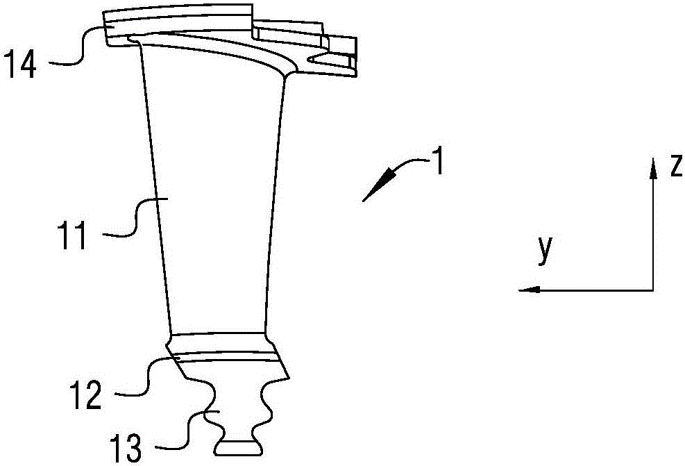
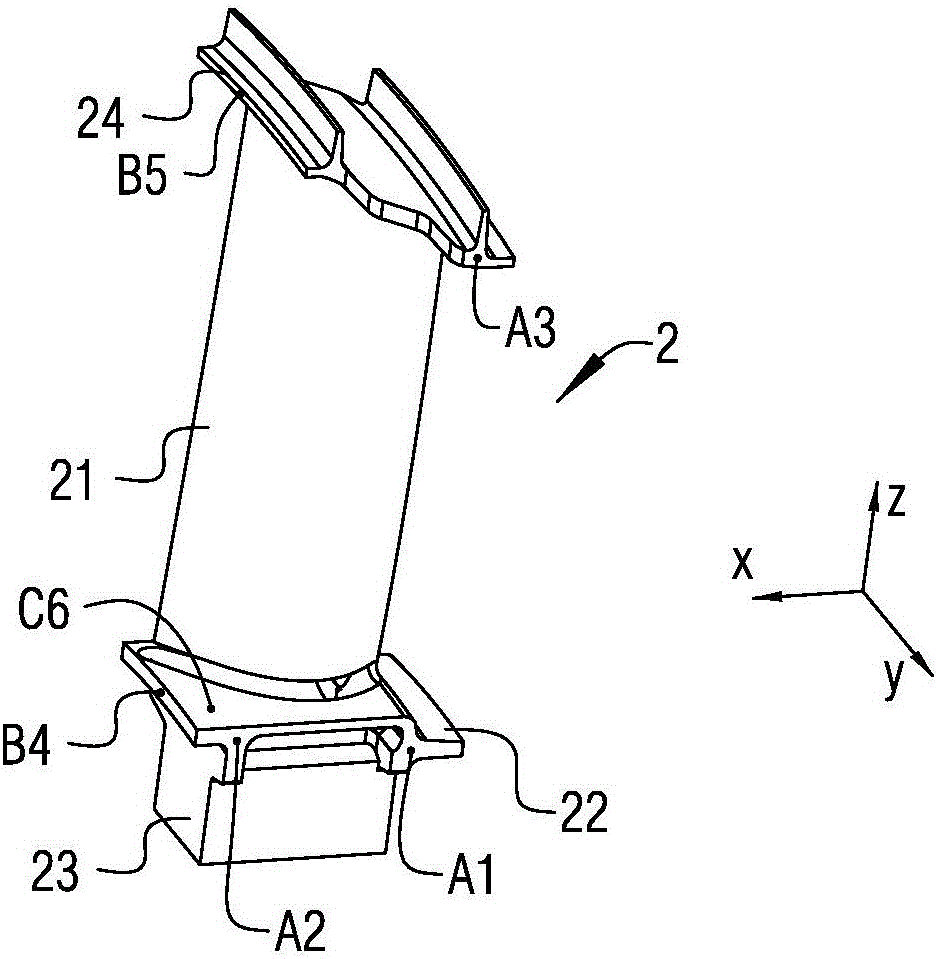
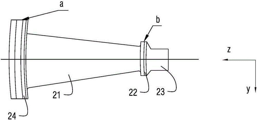
[0027] figure 1 It is a structural schematic diagram of a turbine blade of an aero-engine, figure 2 for the preparation figure 1 Schematic diagram of the structure of the blank of the turbine blade, Figure 4 for figure 2 Schematic diagram of the structure from another angle, Figure 5 It is a schematic structural diagram of a jig used in a crowned turbine blade mortise tooth machining method according to a specific embodiment of the present invention. For the sake of clarity, the three-axis vertical coordinate system is used as a reference in the drawings, where the direction of the z-axis is the axis of the turbine blade 1 and points from the lower edge plate 12 ...


PUM


Abstract

The invention discloses a machining method for a tenon tooth of a shrouded turbine blade. The method includes the steps of A, selecting six positioning points for a blank part and guaranteeing the position dimensions of the positioning points in the process of producing the blank part; B, providing a clamp according to the position dimensions of the positioning points determined in the step A; C, clamping the blank part produced in the step A on the clamp provided in the step B and machining a tenon tooth blank part to form the tenon tooth; and D, carrying out clamping with the tenon tooth as the clamping and locating datum, and machining a lower flange plate and an upper flange plate to complete machining of the turbine blade. According to the machining method for the tenon tooth of the shrouded turbine blade, datum conversion errors can be reduced, accumulated errors caused by datum conversion can be avoided, and the qualification rate of delivery of each time can reach above 90% in actual production.

Description

technical field [0001] The invention relates to the technical field of aero-engines, in particular to a method for machining crowned turbine blade mortise teeth. Background technique [0002] figure 1 It is a structural schematic diagram of a turbine blade of an aero-engine, see figure 1 as shown, figure 1 The turbine blade 1 shown in includes blade body 11, lower edge plate 12, mortise teeth 13 and upper edge plate 14, which has more upper edge plate 14 than ordinary gas turbine blades, that is, more blade crown parts , Therefore, the structure of the turbine blade 1 is usually referred to simply as a shrouded blade. The machining of the turbine blade 1 requires high dimensional accuracy, and its profile is more complex than that of ordinary gas turbine blades, so it is difficult to process, especially the central position of the airfoil 11 is very important to the performance parameters of the engine. [0003] figure 2 for the preparation figure 1 The schematic stru...

Claims


Application Information

Patent Timeline
Patent Type & Authority Applications(China)
IPC IPC(8): B23Q3/06
CPCB23Q3/062
Inventor 黄文俊苏亚涛初文潮易鹏王志杰陈鹰
Owner CHINA HANGFA SOUTH IND CO LTD
Why Eureka
Try Eureka