Rotary stamping machine head and stamping machine

A rotary and stamping machine technology, applied in printing, stamping, etc., can solve the problems of unclear nature of documents, chaotic management, slow switching speed, etc., and achieve the effect of improving stamping efficiency and standardization

Inactive Publication Date: 2017-02-01
周相山
View PDF9 Cites 11 Cited by
  • Summary
  • Abstract
  • Description
  • Claims
  • Application Information

AI Technical Summary

Problems solved by technology

However, traditional stamping equipment needs manual intervention when faced with a large number of complex stamping requirements, especially when facing multiple stamps on a document, it is often necessary to replace the stamp and manually adjust the position, repeating Stamping operations waste a lot of time, and the efficiency of stamping is low; and in the process of using stamps, the management of users is chaotic, illegal use due to unclear nature of documents, overstamping and abuse in advance to save trouble, and illegal purposes The phenomenon of stealing and embezzling has caused a lot of unnecessary losses to the country and enterprises.
[0003] To sum up, most of the existing stamping equipment focuses on mechanical design and has relatively single functions. The main problems are as follows:
[0004] 1. Only one stamp is supported, or multiple stamps are supported but the switching speed is slow and the stamping efficiency is low;
[0005] 2. It is impossible to accurately locate the position of stamping, and the controllability of stamping is poor;
[0006] 3. It does not have the ability to identify the person and document with the seal, and the management level of the seal system is low; therefore, its application range is greatly limited

Method used


Image

  • Rotary stamping machine head and stamping machine
  • Rotary stamping machine head and stamping machine
  • Rotary stamping machine head and stamping machine

Examples


Embodiment Construction

[0031] The rotary stamping machine head and the stamping machine of the present invention will be further described in detail below in conjunction with the accompanying drawings and embodiments.

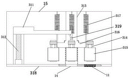
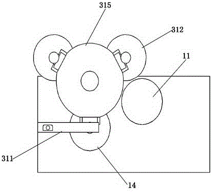
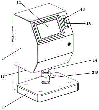
[0032] Such as Figure 1-3 As shown, the rotary stamping machine head, the machine head 1 is provided with a housing 15, and the housing 15 is provided with a rotating mechanism, a stamping mechanism, a pressing mechanism and a fixed table 318; wherein, the rotating mechanism It includes a supporting main shaft 313 and a rotating table 316 , the rotating table 316 is connected to the supporting main shaft 313 through a rotating bearing, and can rotate around the supporting main shaft 313 .

[0033] The lower part of the supporting spindle 313 is fixedly connected with the fixed table 318; the stamping mechanism is arranged on the rotary table 316, and is slidably connected with the rotary table through a slide rail, and a plurality of the stamping mechanisms are arranged along the ci...


PUM


Abstract

The invention provides a rotary stamping machine head and a stamping machine. A shell body 15 is disposed in the machine head 1, and a rotary mechanism, a stamping mechanism, a downward pressing mechanism and a fixation table 318 are disposed in the shell body 15, wherein the rotary mechanism comprises a supporting main shaft 313 and a rotary table 316, and the rotary table 316 is connected to the supporting main shaft 313 by a rotary bearing; the lower part of the supporting main shaft 313 is firmly connected to the fixation table 318; the stamping mechanism is disposed on the rotary table 316, and is in a slide connection with the rotation table by a slide rail; the stamping mechanism comprises a stamp loading mechanism 315; and a connecting rod with an elastic assembly 317 is firmly connected on the stamp loading mechanism 315, and the shell body 15 is connected on the elastic assembly 317. According to the invention, the rotary multi-head stamping mechanism is adopted; a rational translation mechanism and a rational lifting mechanism are designed for the stamping mechanism; a controller is adopted for concentrative control; and rapid switching of multiple stamps can be achieved, and stamping efficiency can be increased greatly.

Description

technical field [0001] The invention relates to the technical field of electromechanical integration control, in particular to a rotary stamping machine head and a stamping machine. Background technique [0002] Seal is an important tool for government agencies, enterprises and institutions to confirm the effectiveness of documents, and it is of great significance to improve its use and management level. However, traditional stamping equipment needs manual intervention when faced with a large number of complex stamping requirements, especially when facing multiple stamps on a document, it is often necessary to replace the stamp and manually adjust the position, repeating Stamping operations waste a lot of time, and the efficiency of stamping is low; and in the process of using stamps, the management of users is chaotic, illegal use due to unclear nature of documents, overstamping and abuse in advance to save trouble, and illegal purposes The phenomenon of stealing cover and...

Claims


Application Information

Patent Timeline
Patent Type & Authority Applications(China)
IPC IPC(8): B41K3/02
Inventor 周相山
Owner 周相山
Why Eureka
Try Eureka