
A connecting shaft misalignment device for automobile steering wheel

A steering wheel and connecting shaft technology, applied to the steering control, steering column and other directions installed on the car, can solve the problems of the steering wheel hurting the driver, performance degradation, lack of rigidity, etc., and achieve a simple and reliable connection structure, high safety, and low cost. Effect

Active Publication Date: 2019-01-29
广州广汽比亚迪新能源客车有限公司
View PDF5 Cites 0 Cited by
  • Summary
  • Abstract
  • Description
  • Claims
  • Application Information

AI Technical Summary

Problems solved by technology

[0002] At present, in order to prevent the steering wheel from moving up and hurting the driver during the collision, a dislocation device is installed in the steering wheel connection shaft of the car. Once a collision occurs, the displacement can occur, which can effectively prevent the steering wheel from moving up. The current dislocation device uses the elasticity of the coil spring. When it hits, the error is relatively large, so the device has certain limitations. In addition, because the coil spring is exposed to the air for a long time, its performance will also decline. So there is a certain risk
[0003] In addition, there are some common car steering wheel connecting shafts. The rod body is divided into two parts. The two parts of the rod body are tangentially connected at the docking part, and then a set of coil springs are fastened outside the docking part of the two parts. The rigidity of the coil spring prevents the The two groups of rods are dislocated, and when a collision occurs, the coil springs are stretched due to insufficient rigidity of the coil springs, causing the two groups of rods to be dislocated, thereby preventing the phenomenon of the steering wheel from moving up and hurting the driver. However, the device still The self-rigidity of the material is used, and because the coil spring is exposed to the air for a long time, its performance will also decrease, so there is a certain danger

Method used


Image

  • A connecting shaft misalignment device for automobile steering wheel
  • A connecting shaft misalignment device for automobile steering wheel
  • A connecting shaft misalignment device for automobile steering wheel

Examples


Embodiment Construction

[0025] The following will clearly and completely describe the technical solutions in the embodiments of the present invention with reference to the accompanying drawings in the embodiments of the present invention. Obviously, the described embodiments are only some, not all, embodiments of the present invention. Based on the embodiments of the present invention, all other embodiments obtained by persons of ordinary skill in the art without making creative efforts belong to the protection scope of the present invention.

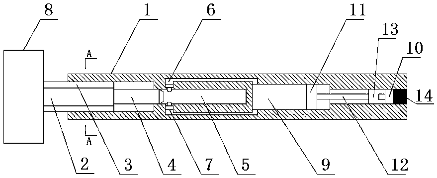
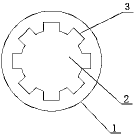
[0026] see figure 1 , figure 2 and image 3 , an embodiment provided by the present invention: a connecting shaft misalignment device for automobile steering wheel, including a housing 1, a rotating shaft 2 and a gear 8 fixed at the bottom of the rotating shaft 2, the inside of the bottom of the housing 1 passes through The tooth structure 3 is connected to the side of the rotating shaft 2, the center of the top of the rotating shaft 2 is fixed with a group...


PUM


Abstract

The invention discloses a connection shaft staggering device for a steering wheel of a car. The connection shaft staggering device comprises a shell, a rotary shaft and a gear fixed to the bottom of the rotary shaft. The interior of the bottom of the shell is connected with the side face of the rotary shaft through a toothed structure. A set of limiting shafts are fixed to the center of the top of the rotary shaft. A hollow structure allowing the limiting shafts to be inserted into is arranged inside the shell. A hollow-out area is arranged on the portion, above the hollow structure, of the interior of the shell. A through hole structure is formed between the hollow-out area and the bottom of the hollow structure and enables the hollow-out area and the hollow structure to communicate with each other. The through hole structure is provided with a set of limiting heads located at the bottom of the hollow structure. A set of pistons are arranged inside the hollow-out area. A set of connection rods are fixed to the centers of the tops of the pistons. The tops of the connection rods are connected with a set of threaded plates. The side faces of the threaded plates are connected with the interior of the shell through thread structures. By means of the connection shaft staggering device, staggering is achieved when a collision occurs. In addition, gas can be supplemented, and the service life is long.

Description

technical field [0001] The invention relates to the technical field of automobile mechanical parts, in particular to a connecting shaft misalignment device for automobile steering wheels. Background technique [0002] At present, in order to prevent the steering wheel from moving up and hurting the driver during the collision, a dislocation device is installed in the steering wheel connection shaft of the car. Once a collision occurs, the displacement can occur, which can effectively prevent the steering wheel from moving up. The current dislocation device uses the elasticity of the coil spring. When it hits, the error is relatively large, so the device has certain limitations. In addition, because the coil spring is exposed to the air for a long time, its performance will also decline. So there is a certain risk. [0003] In addition, there are some common car steering wheel connecting shafts. The rod body is divided into two parts. The two parts of the rod body are tangen...

Claims


Application Information

Patent Timeline
Patent Type & Authority Patents(China)
IPC IPC(8): B62D1/18
CPCB62D1/18
Inventor 刘玲燕
Owner 广州广汽比亚迪新能源客车有限公司
Learn More