Portal crane for assembling motor with weight being above 100T

A technology for gantry cranes and motor stators, applied in cranes, traveling mechanisms, transportation and packaging, etc., can solve problems such as quality accidents, swaying, dangerous and time-consuming, and achieve the effect of assembly quality assurance and elimination of instability

Active Publication Date: 2017-02-01
北京航科机械设备科技有限公司
View PDF7 Cites 4 Cited by
  • Summary
  • Abstract
  • Description
  • Claims
  • Application Information

AI Technical Summary

Problems solved by technology

The entire lifting and installation process is dangerous and time-consuming, because the gap between the stator and the rotor is extremely small by a few millimeters, and the structure of the lifting equipment is long-distance flexible lifting, and it is a hook, which can be lifted at one point. to rotate
When the heavy object is hoisted, there is an inevitable shaking and swinging phenomenon. Once the stator and the rotor collide, scratch, and damage the motor wire package, it will cause a major quality accident. In practice, such accidents often occur

Method used


Image

  • Portal crane for assembling motor with weight being above 100T
  • Portal crane for assembling motor with weight being above 100T
  • Portal crane for assembling motor with weight being above 100T

Examples


Embodiment example 1

[0021] The present invention will be further described below in conjunction with accompanying drawing.

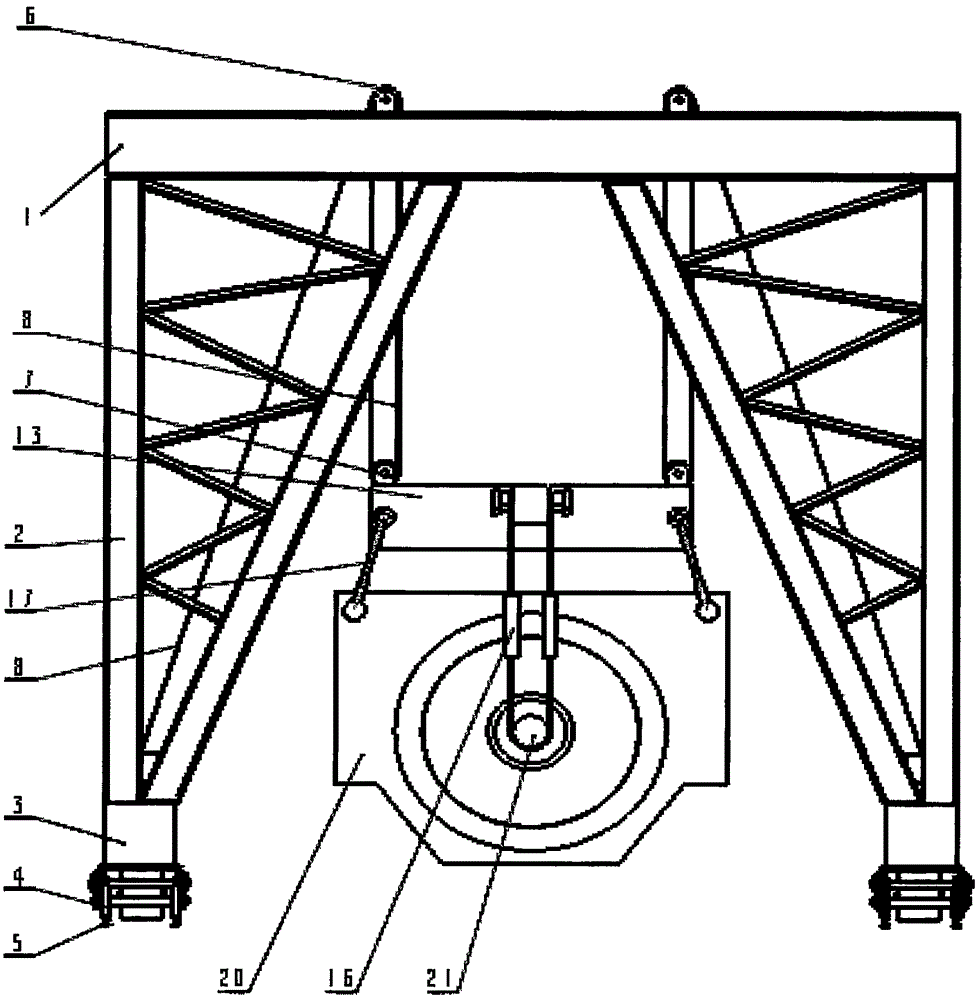
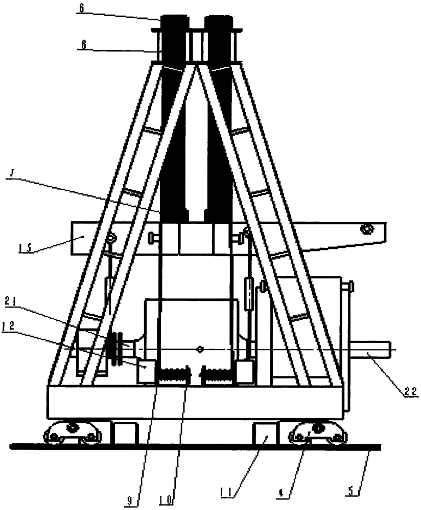
[0022] The invention provides a gantry crane, such as figure 1 As shown, it includes a load-bearing main beam 1 of a portal frame, four inverted triangular columns 2, and a bottom beam 3, wherein the upper ends of the columns are screwed or welded to the main beam, and the lower ends are screwed or welded to the upper plane of the bottom beam. Running mechanism 4 is installed at both ends of the lower plane of the bottom beam, and the speed reducer 11 on the running mechanism 4 can rise and stop on a slope. Double tracks and double tracks 5 are installed on the foundation, and the running mechanism is placed on the track 5.

Embodiment example 2

[0024] like figure 1 and figure 2 As shown, four sets of fixed pulley blocks 6 are installed on the four holes opened on the load-bearing main beam 1 of the portal frame. Fixed on the fixed pulley block 6, the other end is pulled to the reel flange 9 of the hoist 11 on the bottom beam 3 through the last pulley of the fixed pulley block 6. The hoist 11 is equipped with a reducer 12, and four sets are installed on the bottom beam 3. The winches correspond to the four groups of fixed pulley blocks 6 on the load beam 1 respectively.

Embodiment example 3

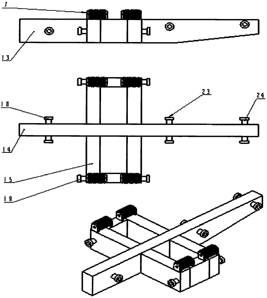
[0026] like image 3 As shown, the Chinese character load beam 13, the central longitudinal long beam 14 is the long beam for the rotor, three suspension points are respectively set according to the center of gravity on the beam, and suspension shafts are installed on each point, which are suspension shaft 18, suspension shaft 23, and suspension shaft respectively. Axis 24. At the center of gravity of the middle beam, a horizontal mouth beam 15 is designed to carry the stator 20. Four suspension shafts 19 are installed at the four corners of the wide side of the mouth beam for hoisting the stator 20. The four corners of the upper plane of the mouth beam 15 are installed Four groups of moving pulley blocks 7 have been developed.


PUM


Abstract

The invention discloses a portal crane for assembling a motor with weight being above 100T. The portal crane comprises a gantry, four pulley blocks, four hoisters, a Chinese character zhong shaped bearing beam and a spreader, wherein the gantry is provided with two running mechanisms and two double rails and double channels, and frequency conversion and speed regulation of the motor are synchronously carried out; four fixed pulley blocks of the pulley blocks and the hoisters are fixed on a bearing main girder, and four movable pulley blocks are fixed on the Chinese character zhong shaped bearing beam; the four hoisters are installed at the middle parts of two bottom beams of the gantry, corresponding to the fixed pulley blocks respectively and lift up and down synchronously; the Chinese character zhong shaped bearing beam is customized according to the stator and rotor hoisting gravity and the geometric shape of the motor; and then, the specially-made steel spreader is used for connection so as to reach the hoisting stability and the assembly accuracy. The portal crane solves the problems of the prior art of swinging, waggling, rotation and vibration in the hoisting and transportation process and has the advantages of simple structure and convenience in operation of equipment, low cost, reliability in assembling the motor, no accident due to quality, high efficacy and the like.

Description

technical field [0001] The invention relates to a new type of lifting equipment, which is used for a gantry crane with a weight of more than 100 tons and a motor assembly. Background technique [0002] Existing giant motors over 100T are assembled with general bridge cranes or gantry cranes. This type of lifting equipment includes lifting trolleys, steel ropes, hooks, slings, and special lifting beams for motor assembly. The beams can be connected to the motor stator or rotor with chain hoists and spreaders. Lift the stator to the installation foundation first, and then lift the rotor. There is a connecting shaft at one end of the rotor shaft. When the rotor end of the connecting shaft passes through the stator and exposes a certain length, support the rotor shaft end with spacers. The sling on the shaft section is unloaded and transposed to the connecting shaft, and then the rotor is hoisted and assembled into the stator. When finished, unload the spreader, and the motor ...

Claims


Application Information

Patent Timeline
Patent Type & Authority Applications(China)
IPC IPC(8): B66C25/00B66C13/06B66C13/08B66C9/14
CPCB66C9/14B66C13/06B66C13/08B66C25/00
Inventor 张新国
Owner 北京航科机械设备科技有限公司
Why Eureka
Try Eureka