Wind generating set yawing device and wind generating set

A wind turbine, yaw technology, applied in wind turbines, wind turbine control, wind power generation, etc., can solve problems such as economic loss, easy jamming, deformation, etc., and achieve the effect of avoiding secondary damage

Inactive Publication Date: 2017-02-01
XEMC WINDPOWER CO LTD
View PDF7 Cites 6 Cited by
  • Summary
  • Abstract
  • Description
  • Claims
  • Application Information

AI Technical Summary

Problems solved by technology

The use of this yaw system avoids the fatigue wear of the caliper hydraulic brake friction plate during yaw, and saves costs, but there are the following defects, which prevent the wind turbine from operating safely and reliably within the expected life cycle:
[0004] 1. The yaw gear is set on the fixed yaw bearing inner ring or the fixed yaw bearing outer ring, and the output pinions at the bottom of multiple yaw gearboxes are engaged with the yaw gear on the yaw bearing for transmission. When the yaw gear and yaw bearing are partially loaded and overloaded, the service life of the yaw gear and yaw bearing will be affected. In particular, when broken teeth occur, after the broken teeth fall on the brake disc , it is easy to get stuck between the meshing of the yaw gear and the output pinion. Once the yaw bearing and the yaw gear are seriously damaged, the entire nose of the wind turbine needs to be hoisted, which will cause huge economic losses
[0005] 2. The yaw braking system of the wind turbine includes a brake disc, a single-top mechanical brake and a caliper hydraulic brake. The braking force of the single-top mechanical brake is provided by a disc spring, and the disc spring will be Due to problems such as loss of elasticity and deformation, the single-top mechanical brake cannot provide stable braking force during the long-term operation of the wind turbine

Method used


Image

  • Wind generating set yawing device and wind generating set
  • Wind generating set yawing device and wind generating set
  • Wind generating set yawing device and wind generating set

Examples


Embodiment Construction

[0018] The present invention will be described in further detail below in conjunction with the accompanying drawings and embodiments.

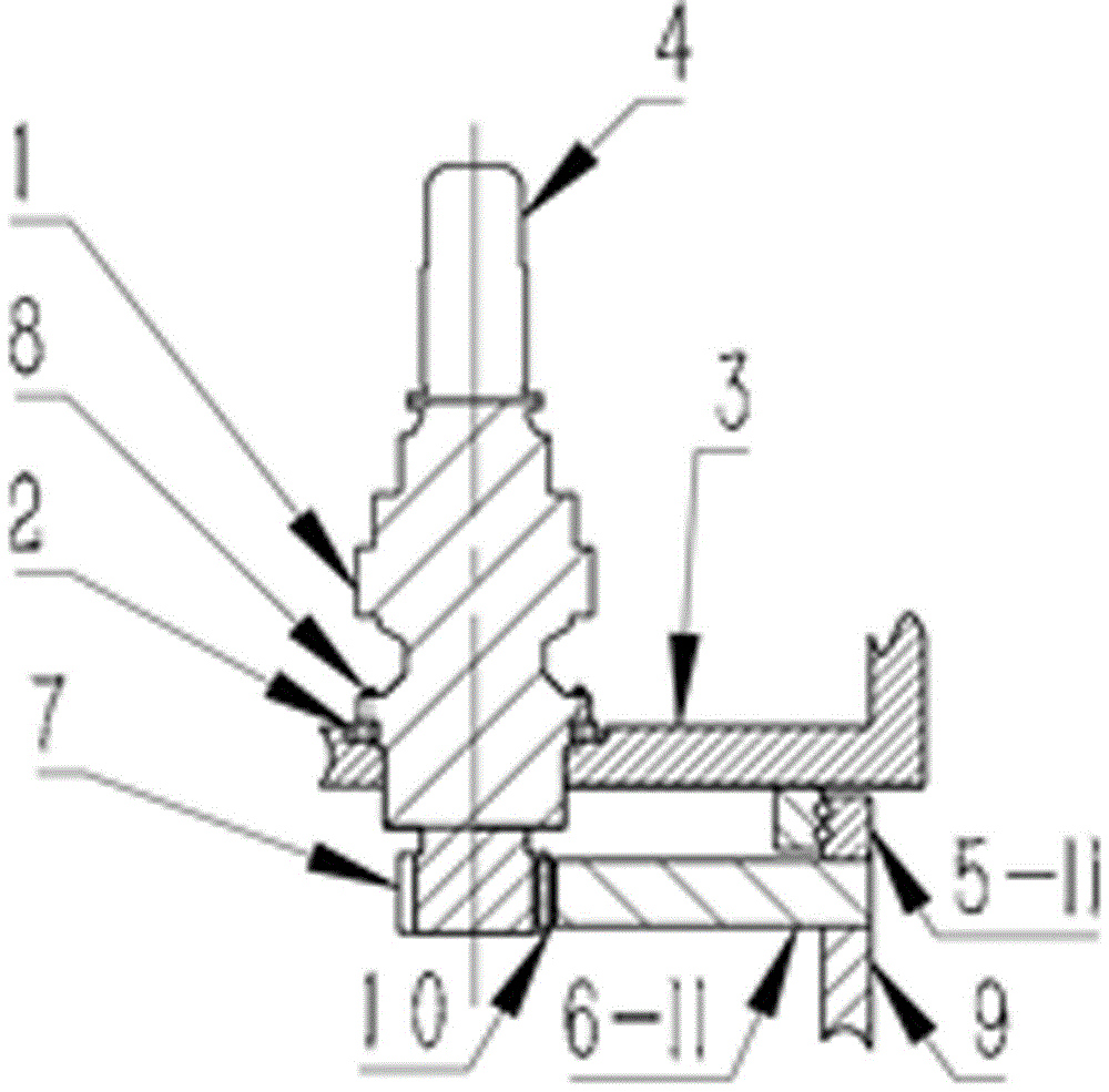
[0019] The present invention specifically provides two embodiments: a wind power generating set suitable for rotating the outer ring of the yaw bearing 5-I and a rotating inner ring of the yaw bearing 5-II when yawing.

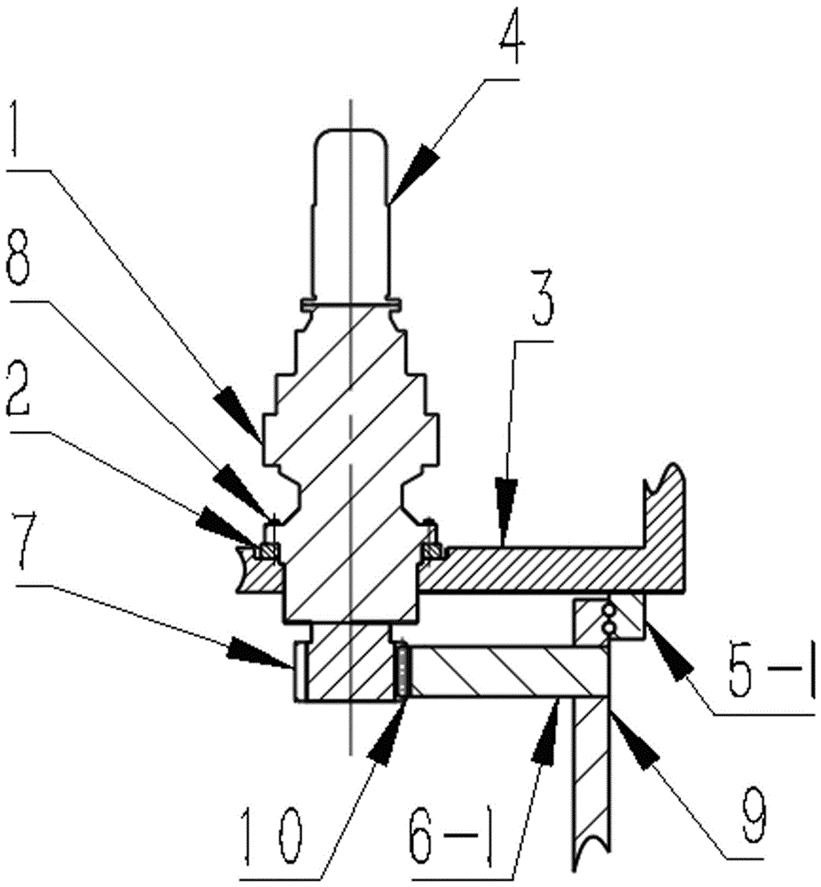
[0020] Refer to attached figure 1 , a kind of wind generator set that is applicable to the rotation of yaw bearing 5-1 outer ring during yaw, its yaw drive system includes: nacelle 3, tower tube 9, yaw motor 4, yaw gearbox 1, yaw bearing 5-I and brake disc 6-I. The brake disc 6-I is located between the upper surface of the tower tube 9 and the lower surface of the yaw bearing 5-I, and is fixedly connected with the inner ring of the yaw bearing 5-I. Preferably, the yaw bearing 5 is a double-row four-point angular contact ball bearing preloaded with negative clearance. The yaw gearbox 1 is fixed with the yaw motor 4 on the to...


PUM


Abstract

The invention relates to a wind generating set yawing device. The device comprises a brake disc, a yawing gear, a yawing bearing and a yawing gearbox; the yawing gearbox is fixed to an engine room, the brake disc and an inner ring or an outer ring of the fixed yawing bearing are fixed together, and the yawing gear is arranged on the inner side of the brake disc, and is engaged with multiple output small gears at the bottom of the yawing gearbox. Due to the fact that the yawing gear is arranged on the inner side of the brake disc, when engaging tooth breaking appears in the position between the yawing gear and the small gears, broken teeth can fall down from the lower portion in time, and cannot be clamped in engaging portions of the yawing gear and the output small gears, and secondary damage of the gear is avoided. The invention further relates to a wind generating set with the yawing device.

Description

technical field [0001] The invention relates to the field of wind power generation, in particular to a yaw device for a wind power generating set and a wind power generating set. Background technique [0002] The wind turbine yaw device is an important part of the wind turbine, which consists of a yaw drive system and a yaw brake system. The yaw device of a large megawatt wind turbine is usually provided with a yaw gear on the fixed inner ring of the yaw bearing or the outer ring of the fixed yaw bearing. When the wind direction changes, it is driven by the yaw installed on the nacelle to The way the gears mesh drives the yaw bearing to rotate. On the other hand, the brake disc is fixedly connected with the tower, and the brake provides braking force by applying pressure to the brake disc, so as to prevent the nacelle from deviating from the target position under the action of inertia and external load, and ensure the safe and reliable operation of the wind turbine . [0...

Claims


Application Information

Patent Timeline
Patent Type & Authority Applications(China)
IPC IPC(8): F03D7/02F03D15/10
CPCF03D7/0204F03D7/0244Y02E10/72
Inventor 章滔何录忠王石林阳雪兵尹耀安
Owner XEMC WINDPOWER CO LTD
Why Eureka
Try Eureka