
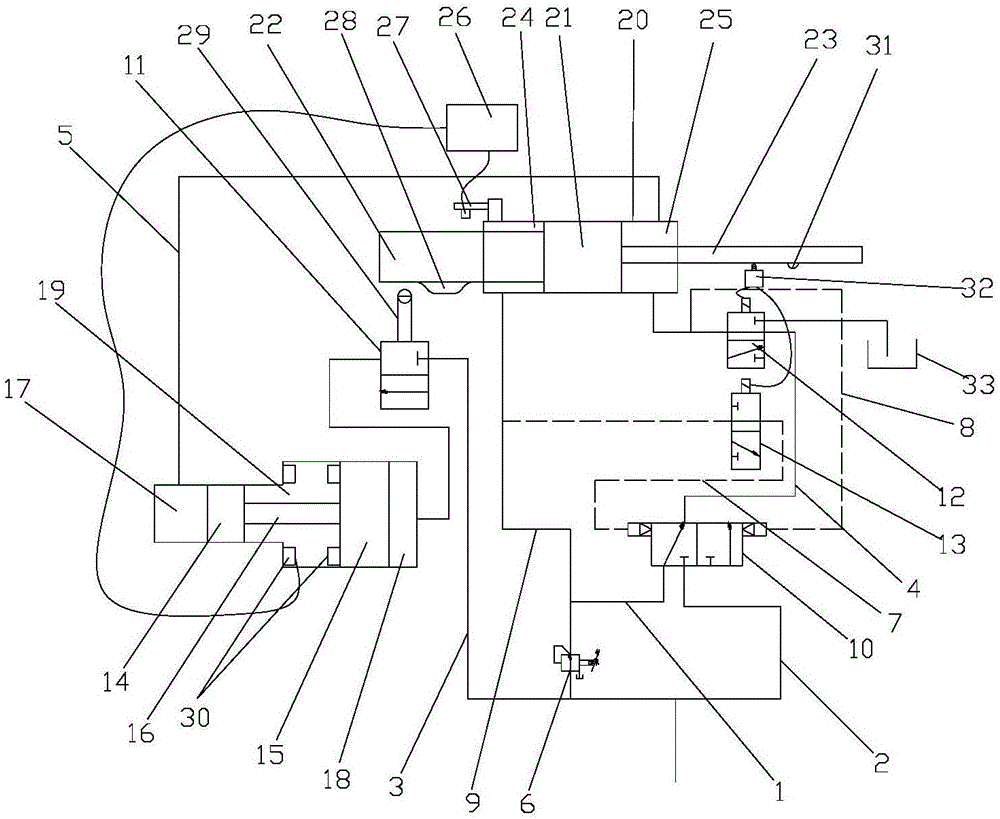
Electro-hydraulic control pressure machine

An electro-hydraulic control and pressure technology, applied in the direction of mechanical equipment, fluid pressure actuators, servo motors, etc., can solve the problems of slow response to pressure changes, unstable return speed, complex return control of the stamping rod, etc., to achieve good rigidity, The effect of low scrap rate

Active Publication Date: 2017-02-01
青岛明晖精锻设备有限公司
View PDF6 Cites 0 Cited by
  • Summary
  • Abstract
  • Description
  • Claims
  • Application Information

AI Technical Summary

Problems solved by technology

[0007] 1. The return stroke control of the stamping rod is complicated, and the return stroke response is not more sensitive
[0008] 2. When the stamping rod returns, the return speed is unstable, resulting in different return times each time
[0009] 3. The feed speed of the first stage and the second stage of the stamping rod is unstable, and the response to pressure changes is slow

Method used


Image

  • Electro-hydraulic control pressure machine

Examples


Embodiment Construction

[0029] In order to enable those skilled in the art to better understand the technical solutions of the present invention, the present invention will be described in detail below in conjunction with the accompanying drawings and specific embodiments.

[0030] Before introducing the electro-hydraulic control pressure machine of the present invention, the process of stamping deformation of the stamped workpiece and the several strokes of the stamping rod 22 (or ram) of the stamped workpiece in the entire stamping process are firstly introduced so that the present invention can be deeply understood technical solutions and friendship effects.

[0031] It is traditionally believed that the workpiece needs to be subjected to sufficient and constant pressure before it can be formed. However, in the actual deformation of the workpiece, the pressure required for different stages of deformation is different. The workpiece undergoes two kinds of deformation from the blank to the molding. ...


PUM


Abstract

The invention discloses an electro-hydraulic control pressure machine used for stamping workpieces. The machine comprises an execution mechanism and a hydraulic control mechanism which provides pressure for the execution mechanism and controls the execution mechanism. The hydraulic control mechanism comprises a first hydraulic pipeline, a second hydraulic pipeline, a third hydraulic pipeline, a pressure reducing valve, a first control unit, a pressurization mechanism, a second control unit and a magnetic control mechanism. The pressurization mechanism and the magnetic control mechanism are arranged in the hydraulic control mechanism, pressure is continuously increased when the pressurization mechanism and the magnetic control mechanism are matched for enabling a stamping rod to enter a third stroke section to cause elasticoplastic deformation of the workpieces, and therefore the requirement of the workpieces for continuously increasing pressure during elasticoplastic deformation is met. Due to the fact that the stamping rod adapts to pressure changes of three stroke sections through the hydraulic control mechanism, the stamped workpieces are good in rigidity, and the rejection rate of the stamped workpieces is low.

Description

technical field [0001] The invention relates to the electromechanical field, in particular to an electro-hydraulic control pressure machine. Background technique [0002] In the prior art, two types of power are usually used for stamping workpieces. One is to use mechanical transmission as the power, that is, mechanical power; the other is to use hydraulic transmission as the power, that is, hydraulic power. Generally, when the deformation of the workpiece is reduced, the elastic-plastic modulus of the workpiece is small, and the pressure required for the deformation of the workpiece is small, it is more appropriate to use mechanical power, because the mechanical power makes the stamping action of the stamping rod faster. When the deformation of the workpiece is large, and the elastic-plastic modulus of the workpiece is large, and the pressure required for the deformation of the workpiece is large, it is more appropriate to use hydraulic power, because hydraulic power can pr...

Claims


Application Information

Patent Timeline
Patent Type & Authority Applications(China)
IPC IPC(8): F15B11/00
CPCF15B11/00
Inventor 高凤婷
Owner 青岛明晖精锻设备有限公司
Learn More