An energy-feeding magnetorheological fluid energy absorber

An energy absorber and magnetorheological fluid technology, applied in the field of actuators, can solve the problems of increased installation space requirements for the complexity of the cost system, difficult application environment for magnetorheological fluid energy absorbers, and bulky energy absorbers, etc. To achieve the effect of compact structure, application cost saving and cost reduction

Active Publication Date: 2019-03-08
合肥庐阳科技创新集团有限公司
View PDF5 Cites 0 Cited by
  • Summary
  • Abstract
  • Description
  • Claims
  • Application Information

AI Technical Summary

Problems solved by technology

First, the high price of magnetorheological fluid is dozens of times that of ordinary hydraulic oil. Most of the traditional magnetorheological fluid energy absorbers are modified based on the structure of hydraulic energy absorbers. The consumption of magnetorheological fluid Comparable to hydraulic oil, the cost of the final manufactured magneto-rheological fluid energy absorber is dozens of times higher than that of hydraulic energy absorbers
For example, the magnetorheological fluid energy absorber used in bridge construction is bulky and the actual activity stroke is short, resulting in most of the magnetorheological fluid filled in the energy absorber being in an idle state, with a large amount of use and low efficiency (less than 0.4vol%) )
Second, the magnetorheological fluid semi-active system requires an additional power supply, which increases the complexity of the system and takes up additional installation space, which makes it difficult for the magnetorheological fluid energy absorber to be successfully applied to automobile suspensions or other interiors Applications with limited space
Third, system controllers and state feedback sensors are modules that must be configured in most traditional magnetorheological fluid semi-active systems. Complex control strategies correspond to complex control modules, which will inevitably lead to system costs and system complexity. degree and the corresponding increase in the installation space requirements, the reliability of the system will be reduced accordingly

Method used


Image

  • An energy-feeding magnetorheological fluid energy absorber
  • An energy-feeding magnetorheological fluid energy absorber
  • An energy-feeding magnetorheological fluid energy absorber

Examples


Embodiment approach

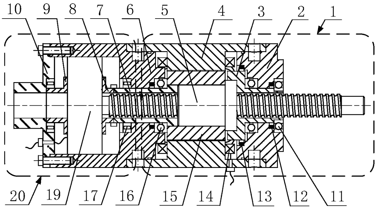
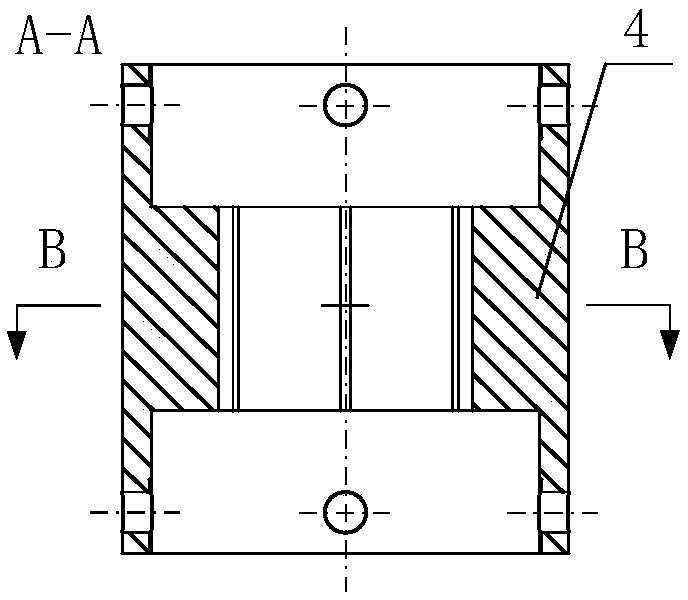
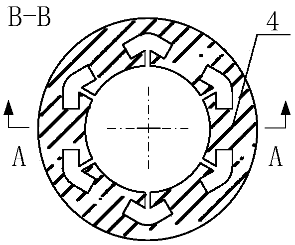
[0058] figure 1 , Figure 2a , Figure 2b , Figure 3a , Figure 3b as well as Figure 4 One embodiment of the invention is shown in the form of:

[0059] Such as figure 1 As shown, the mechanical structure of the energy-feeding magnetorheological fluid energy absorber is composed of a controllable damping force mechanism 1 and an energy-feeding mechanism 20; the controllable damping force mechanism 1 is coaxially assembled by a cylindrical excitation shell 4 and a motion conversion mechanism Composition, the excitation shell 4, the upper end cover 2, and the energy feeding mechanism shell 6 jointly form a closed space filled with magnetorheological fluid, and the closed liquid cavity is filled with magnetorheological fluid, about 82ml; the motion conversion mechanism is composed of the conversion mechanism sleeve 3, The ball screw 5, the excitation rotor 15 and the thrust bearing 16 are coaxially assembled. The outer circumferential surface of the excitation rotor 15 an...


PUM


Abstract

The invention discloses an energy feedback type magnetorheological fluid energy absorber. The energy feedback type magnetorheological fluid energy absorber is characterized in that the energy feedback type magnetorheological fluid energy absorber is composed of a controllable damping force mechanism, an energy feedback mechanism and a self-adaption power supply circuit; the controllable damping force mechanism is formed by coaxially assembling an excitation shell and a movement conversion mechanism, wherein the movement conversion mechanism comprises a conversion mechanism sleeve, a ball screw, an excitation rotor and a thrust bearing; the excitation shell is connected with an upper end cover and an energy feedback mechanism shell to form a closed space full filled with magnetorheological fluid; according to the energy feedback mechanism, in the energy feedback mechanism shell, an engine is formed by coaxially assembling an engine upper sleeve and an engine lower sleeve, and an engine is driven through a rotating connection sleeve so that energy feedback can be achieved; and electric connection of the self-adaption power supply circuit is achieved between the energy feedback output end of the energy feedback mechanism and the power supply input end of the controllable damping force mechanism. By means of the energy feedback type magnetorheological fluid energy absorber, efficient utilization of the magnetorheological fluid is achieved, and the self-adaption power supply function of the magnetorheological fluid energy absorber is achieved.

Description

technical field [0001] The invention relates to an actuator for energy harvesting and vibration / shock control systems, and more particularly to an energy-feeding magnetorheological fluid energy absorber. Background technique [0002] Shock and vibration exist in various fields and are unavoidable, such as: ground vehicles driving on uneven roads, aircraft landing shocks, buildings encountering seismic waves, vibrations generated by mechanical equipment and working instruments, etc. These vibrations / shocks have adverse effects on people's work and life. The use of energy absorbers, that is, shock absorbers, can absorb and buffer vibrations and shocks, not only to ensure the stability and safety of mechanical equipment and instrument systems during operation, but also to enhance the vehicles, aircraft and other vehicles to provide loads or occupants comfort. [0003] Traditional energy absorbers based on smart material magnetorheological fluids can provide damping forces of ...

Claims


Application Information

Patent Timeline
Patent Type & Authority Patents(China)
IPC IPC(8): F16F9/53F16F9/512F16F9/32
CPCF16F9/3207F16F9/5123F16F9/535F16F2222/12
Inventor 白先旭邹棋钱立军
Owner 合肥庐阳科技创新集团有限公司
Why Eureka
Try Eureka