Floor type air conditioner indoor unit and control method thereof

A floor-standing air conditioner and indoor unit technology, applied in airflow control components, heating and ventilation control systems, heating methods, etc., can solve problems such as user discomfort and affect user experience, and achieve a good user experience

Active Publication Date: 2017-02-01
WUHU MATY AIR CONDITIONING EQUIP CO LTD +1
View PDF8 Cites 8 Cited by
  • Summary
  • Abstract
  • Description
  • Claims
  • Application Information

AI Technical Summary

Problems solved by technology

[0003] The technical problem to be solved by the present invention is: in the existing air-conditioning indoor unit, the temperature in the room is changed by blowing cold wind or hot wind directly into the room, but when the cold wind or hot wind blows directly on the user, the user will feel uncomfortable and affect the temperature of the room. Therefore, it is necessary to provide a floor-mounted air conditioner indoor unit that can provide cooling and heat to the room and avoid direct blowing of cold wind or hot wind

Method used


Image

  • Floor type air conditioner indoor unit and control method thereof
  • Floor type air conditioner indoor unit and control method thereof
  • Floor type air conditioner indoor unit and control method thereof

Examples


Embodiment 1

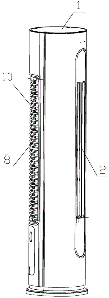
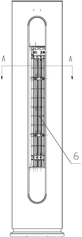
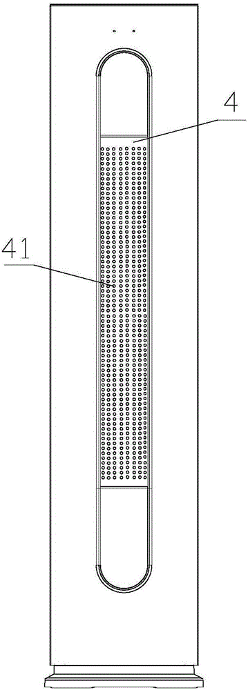
[0047] Such as Figure 1 to Figure 16 As shown, the floor-standing air conditioner indoor unit provided by the present invention includes a housing 1, a diffuser panel 4, an air outlet frame 11, an appearance panel 7, an air duct assembly and a first switching device 3, and the housing 1 is cylindrical , the casing 1 forms an accommodating cavity, and the appearance panel 7, the air diffuser panel 4, the air outlet frame 11 and the air duct assembly are all located in the accommodating cavity; the casing 1 is provided with an air inlet 8 and an air outlet 2, The air duct assembly is located between the air inlet 8 and the air outlet 2, and the air duct assembly includes a cross-flow fan and an air flow channel 15 formed by the air duct wall 14 in the accommodating cavity, and the cross-flow fan is arranged in the air flow channel 15, the other end of the air flow channel 15 communicates with the air outlet 2; the wind guide vane 6 is installed on the air outlet frame 11, and t...

Embodiment 2

[0061] This embodiment is basically the same as the technical solution in Embodiment 1, the main difference is that the upper end or the lower end of the overall arc-shaped plate is provided with a first switching device 3, and the overall arc-shaped plate is in phase with the first switching device 3. The corresponding lower end or upper end is also provided with a transmission device, the first switching device 3 and the transmission device are installed between the overall arc-shaped plate and the air outlet frame 11, and the overall arc-shaped plate passes through the first switching device 3 and the air outlet frame 11. Driven jointly by the transmission device, the air outlet 2 can be opened or closed by circumferential movement. The structure of the transmission device is similar to that of the first switching device 3 , except that the first driving motor 31 is not included.

[0062] The present invention also provides a control method for the indoor unit of the floor-...


PUM


Abstract

The invention relates to a floor type air conditioner indoor unit and a control method thereof. The floor type air conditioner indoor unit comprises a shell. A containing cavity is formed in the shell. An air spreading panel, an appearance panel, an air outlet frame and an air channel assembly are all located in the containing cavity. The air spreading panel and the appearance panel are installed together to form an integral arc panel. The integral arc panel is installed on one side of the air outlet frame. The integral arc panel is driven by a first switching device to move in the circumferential direction so that an air outlet can be opened and closed. Micro air spreading holes are formed in the air spreading panel. In the conventional normal air outlet process, the integral arc panel is contained in the shell, when a breeze outlet mode needs to be started, the side, provided with the air spreading panel, of the integral arc plate moves to the position of the air outlet along a circumferential rack through the first switching device, the air outlet is completely blocked, concentrated hard airflow subjected to heat exchange is spread through the micro air spreading holes in the air spreading panel and consequently becomes softer, and the cool/hot feel and the air-free feel are achieved.

Description

technical field [0001] The invention relates to the technical field of household appliances, in particular to an indoor unit of a floor-standing air conditioner and a control method thereof. Background technique [0002] At present, air conditioners, as a household appliance, have been gradually applied to ordinary families. The air conditioner includes an indoor unit and an outdoor unit. In the existing indoor units of the air conditioner, cold air or hot air is blown outwards through the air outlet to provide cooling or heat to the room. , blowing to the indoor user will cause the user to feel too cold or overheated, and the user will feel uncomfortable, which will affect the user's experience. Contents of the invention [0003] The technical problem to be solved by the present invention is: the existing air-conditioning indoor unit blows cold wind or hot wind directly into the room to change the temperature in the room, but when the cold wind or hot wind blows directly...

Claims


Application Information

Patent Timeline
Patent Type & Authority Applications(China)
IPC IPC(8): F24F13/22F24F13/24F24F13/14F24F13/08F24F13/30F24F11/00F24F7/06
CPCF24F11/0001F24F13/082F24F13/1426F24F13/22F24F13/24F24F13/30F24F2013/1433F24F2013/1446F24F2013/221F24F2013/247Y02B30/70
Inventor 刘阳蔡序杰彭杰林
Owner WUHU MATY AIR CONDITIONING EQUIP CO LTD
Why Eureka
Try Eureka