Walking beam furnace

A walking heating furnace and heating chamber technology, applied in the direction of lighting and heating equipment, furnace, furnace type, etc., can solve the problems of affecting heating efficiency, transportation confusion, easy to change the distance between steel pipes, etc., and achieve the effect of reducing heating efficiency

Inactive Publication Date: 2017-02-01
长兴吉成工业炉有限公司
View PDF8 Cites 1 Cited by
  • Summary
  • Abstract
  • Description
  • Claims
  • Application Information

AI Technical Summary

Problems solved by technology

[0002] The heating furnace plays a very important role in the production of steel pipes. The structure of the traditional steel pipe heating furnace is an ordinary inclined bottom furnace. Overheating furnace, so that the process of heating steel pipes can be completed in a streamlined manner during the transportation of steel pipes, but in the actual production process of steel pipes, the steel pipes in the heating furnace need to be fully heated, which requires preheating and reheating steps. The speed of conveying in the heating furnace for a single steel pipe to complete this step is generally lower than the normal conveying track, so it is easy to transport confusion here, resulting in inconsistent gaps and quantities of steel pipes in the heating furnace, which ultimately affects the overall quality. Heating efficiency has a great influence on the quality of steel pipe after forming
[0003] The existing technology uses conveying tracks with different conveying speeds to pass through the steel pipes, and uses a manual pipe pulling device to move the steel pipes from the normal conveying track to the conveying track of the heating furnace. The distance between the steel pipes, and the steel pipes entering the heating furnace in this state are prone to surface adhesion and other quality problems under the action of heating, and the labor intensity is high

Method used


Image

  • Walking beam furnace
  • Walking beam furnace
  • Walking beam furnace

Examples


Embodiment Construction

[0024] The present invention will be described in further detail below in conjunction with the accompanying drawings.

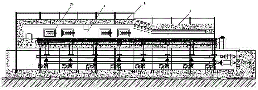
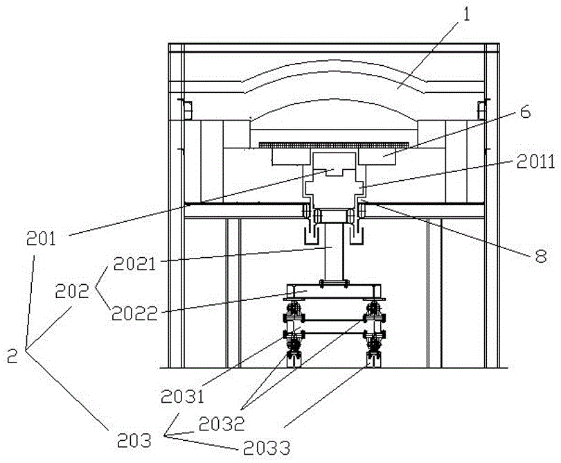
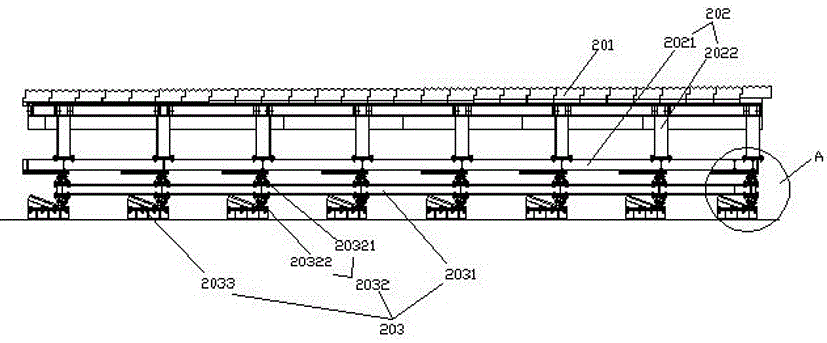
[0025] Such as Figure 1 to Figure 4 As shown, the embodiment of the present invention includes a furnace body 1 and a conveying device 2. In the furnace body 1, a preheating chamber 3 and a heating chamber 4 connected to each other are sequentially arranged along the feeding direction to the discharging direction. The height of the preheating chamber 3 is less than The height of the heating chamber 4. The inner wall of the furnace body 1 is made of fireproof material. The conveying device 2 passes through the preheating chamber 3 and the heating chamber 4. A heating device 5 is arranged in the heating chamber 4. The heating device 5 is arranged above the conveying device 2. The heating device 5 is mainly realized by means of a hot air blower. The conveying device 2 at least includes a conveying platform 201, a translation mechanism 202 that moves the conve...


PUM


Abstract

The invention discloses a walking beam furnace. The walking beam furnace comprises a furnace body, a conveying device and a heating device; the conveying device at least comprises a conveying table, a horizontal moving mechanism moving the conveying table in the horizontal direction and a lifting mechanism lifting the conveying table in the vertical direction, wherein the horizontal moving mechanism is connected under the conveying table and is movably connected to the lifting mechanism in a linear mode in the horizontal direction; and supporting tables are arranged in the furnace body and are arranged on two sides of the conveying table in parallel. According to the walking beam furnace, the conveying device is matched with a supporting structure in the furnace body to transfer steel pipes in a circulation mode of lifting, horizontal moving and laying down.

Description

technical field [0001] The invention relates to the field of steel pipe production equipment, in particular to a walking heating furnace. Background technique [0002] The heating furnace plays a very important role in the production of steel pipes. The structure of the traditional steel pipe heating furnace is an ordinary inclined bottom furnace. Overheating furnace, so that the process of heating steel pipes can be completed in a streamlined manner during the transportation of steel pipes, but in the actual production process of steel pipes, the steel pipes in the heating furnace need to be fully heated, which requires preheating and reheating steps. The speed of conveying in the heating furnace for a single steel pipe to complete this step is generally lower than the normal conveying track, so it is easy to transport confusion here, resulting in inconsistent gaps and quantities of steel pipes in the heating furnace, which ultimately affects the overall quality. The heati...

Claims


Application Information

Patent Timeline
IPC IPC(8): F27B9/20F27B9/30
CPCF27B9/201F27B9/203
Inventor 罗来军严霆彭李伟
Owner 长兴吉成工业炉有限公司
Why Eureka
Try Eureka