Locating device for measuring tubular parts

A technology for positioning devices and tubular parts, which is applied in the direction of positioning devices, measuring devices, metal processing machinery parts, etc., can solve the problems of difficulty in guaranteeing machining accuracy and difficult processing of tubular parts with large length-to-diameter ratio, and achieve improved measurement accuracy and high The value of engineering application and the effect of simplifying the inspection process

Active Publication Date: 2017-02-01
CHINA NUCLEAR TIANJIN TECH DEV
View PDF7 Cites 8 Cited by
  • Summary
  • Abstract
  • Description
  • Claims
  • Application Information

AI Technical Summary

Problems solved by technology

[0002] Large length-to-diameter ratio tubular parts are difficult to process, and the processing accuracy is difficult to guarantee. Inspections need to be carried out one by one to control product quality.

Method used


Image

  • Locating device for measuring tubular parts
  • Locating device for measuring tubular parts
  • Locating device for measuring tubular parts

Examples


Embodiment Construction

[0024] The positioning device for tubular member measurement of the present invention will be described in detail below in conjunction with the drawings and embodiments of the description:

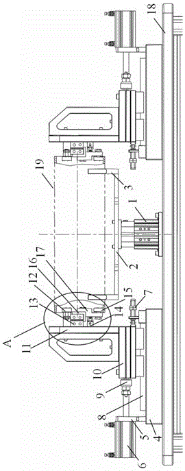
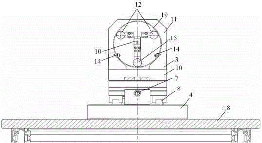
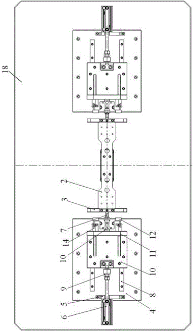
[0025] Such as Figure 1~4 As shown, a positioning device for tubular member measurement, including a lifting mechanism and a pair of left-right symmetrical and concentric positioning mechanisms;

[0026] The lifting mechanism includes a lifting cylinder 1, a connecting plate 2 connected to the lifting cylinder 1 cylinder bar and a V-shaped positioning frame 3 symmetrically arranged at both ends of the upper end surface of the connecting plate 2;

[0027] The lifting cylinder 1 is a cylinder that can be loaded with a magnetic switch, and is used for feedback control signals to realize automatic control; its upper and lower ends are provided with standard screw holes, which are respectively used to connect the frame plate 18 and the connecting plate 2;

[0028] The connecting plate 2 is pr...


PUM


Abstract

The invention discloses a locating device for measuring tubular parts. The locating device comprises a lifting mechanism and a pair of locating mechanisms which are bilaterally symmetrical and arranged in a concentric way, wherein the lifting mechanism comprises a lifting cylinder, a connecting plate connected with a cylinder rod of the lifting cylinder, and two V-shaped locating racks which are symmetrically arranged at two ends of the upper end face of the connecting plate; each locating mechanism comprises a bottom plate, a feed cylinder arranged on the bottom plate, a hydraulic buffer and a linear guide rail pair; a universal connector is arranged at the front end of a cylinder rod of each feed cylinder; a sliding block is arranged on each linear guide rail pair; a vertical plate is arranged on the upper top surface of each sliding block; an inner support bearing pair, a miniature cylinder and a limiting bearing pair are arranged on the end face of the side, close to the tubular part, of each vertical plate; tensioning bearings are connected with cylinder rods of the miniature cylinders by connecting blocks I and connecting blocks II. After the locating device is used, a plurality of test items can be measured by clamping and locating at a time, so that the inspection process is greatly simplified, the detection working procedures are reduced, and the detection efficiency and the measurement accuracy are improved.

Description

technical field [0001] The invention belongs to a workpiece positioning device, in particular to a positioning device for measuring a tubular part. Background technique [0002] The processing of tubular parts with large length-to-diameter ratio is difficult, and the processing accuracy is difficult to guarantee. Inspections need to be carried out one by one to control product quality. Especially for the detection of parameters such as diameter, roundness and wall thickness uniformity of tubular parts, the workpiece needs to be rotated to meet the requirements of the measurement point. Under normal circumstances, if the outer surface of the tested tubular part is relatively smooth, the outer circular chord positioning can be combined with an appropriate driving method to realize the measurement; when the outer surface roughness of the tested part cannot meet the requirements, the inner cavity positioning should be considered. Especially for tubular parts with many testing i...

Claims


Application Information

Patent Timeline
Patent Type & Authority Applications(China)
IPC IPC(8): G01B21/00B23Q3/18
CPCG01B21/00B23Q3/18
Inventor 王斌齐铁成陈景华王广新崔丽兰张静辰
Owner CHINA NUCLEAR TIANJIN TECH DEV
Why Eureka
Try Eureka