A bench for testing the braking system of automobiles and trains

A braking system and automobile train technology, which is applied in the field of automobile train braking system detection, can solve the problems of waste of site resources, inability to detect the overall performance of the braking system, and lack of a braking system performance testing platform, etc. land area effect

Active Publication Date: 2018-11-09
徐州花千树农业发展有限公司
View PDF8 Cites 0 Cited by
  • Summary
  • Abstract
  • Description
  • Claims
  • Application Information

AI Technical Summary

Problems solved by technology

The defects of the above two inventions are: they are all testing benches for individual components in the braking system, and cannot provide testing conditions for other components, and cannot detect the overall performance of the braking system
[0005] Chinese Patent Publication No. CN104990713A proposes an automobile brake assembly fatigue test bench, including a base and a constant temperature box. The defect of this invention is that it can only be used for the detection of automobile brake assemblies, and cannot be used for the detection of automobile train brake systems. , and when the test bench is not working, its floor space is the same as that of the working floor, resulting in a waste of site resources
[0006] The existing test bench is mainly aimed at the detection of specific individual components of the braking system, which has poor versatility, and there is no bench for performance testing of the brake system of automobiles and trains. In addition, when the test bench is not working, the bench cannot be adjusted to reduce the Small footprint, resulting in waste of site resources

Method used


Image

  • A bench for testing the braking system of automobiles and trains
  • A bench for testing the braking system of automobiles and trains
  • A bench for testing the braking system of automobiles and trains

Examples


Embodiment Construction

[0032] The present invention will be further described below with reference to the accompanying drawings and specific embodiments, but the protection scope of the present invention is not limited thereto.

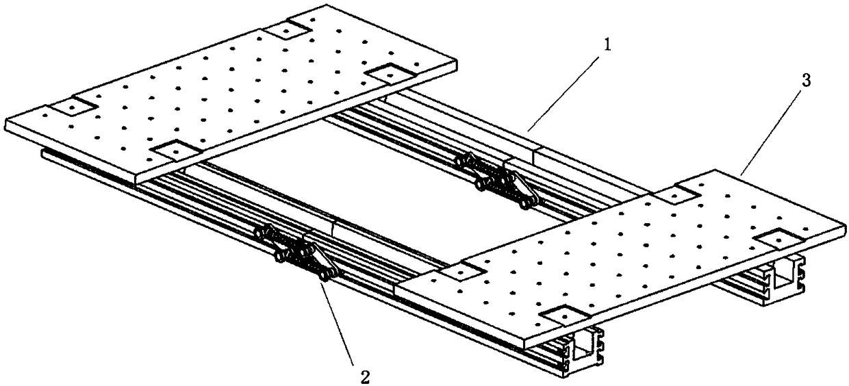
[0033] like figure 1 As shown, the test bench of the automobile train braking system of the present invention includes parallel rails and a movable platform 3 , and each rail at least includes two sections of guide rails 1 , a link mechanism 2 and a limit bolt 4 .

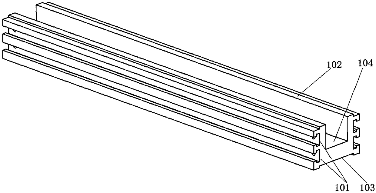
[0034] like figure 2 As shown, the guide rail 1 is provided with a chute 104 along the axis direction, and two "T"-shaped grooves 101 are respectively provided on the outer sides of the two side walls of the chute 104. The two ends of the "T"-shaped groove 101 A screw hole is provided, and the limit bolt 4 is installed on the guide rail 1 through the screw hole to limit the displacement of the link mechanism in the "T"-shaped groove; the upper surfaces of the two side walls of the chute 104 are convex Table 1...


PUM


Abstract

The invention provides a vehicle and train braking system detection applied stand which comprises a guide rail, a connection rod mechanism, a mobile platform and a position limiting bolt. The connection rod mechanism is sleeved in the T shaped concave grooves at two sides of the guide rail. The mobile platform is arranged on the guide rail. The foot wheels at the bottom of the mobile platform can slide in the sliding grooves of the guide rails. The mobile platform is connected with the bolt through a connection module. The guide rail is connected with the position limiting bolt through the connection rod mechanism. According to the invention, it is possible to simulate vehicle wheelbases of different lengths when the numbers of the guide rail and the mobile platform vary. Through the splicing of the mobile platforms, braking systems of different dimensions can be made so as to meet the detection requirement for different braking systems. In addition, the connection rod mechanism realizes the rapid and organized folding and placing of the guide rail, which effectively reduces the area occupied by the testing stand.

Description

technical field [0001] The present invention relates to a test stand, in particular to the test of an automobile train braking system. Background technique [0002] my country's road freight transportation industry is in a stage of rapid development and occupies an important position in the comprehensive transportation service system. Among them, car trains play a pivotal role as one of the main vehicles in the road transportation system. Studies have shown that the braking system of automobiles and trains is one of the important factors affecting its driving safety, and its poor braking performance or failure may directly lead to traffic accidents. Therefore, it is particularly important to detect the braking system of automobile trains. [0003] Usually, the main components of the braking system, such as brakes, brake master cylinders, brake valves, etc., need to be tested on the test bench. At the same time, the overall performance of the braking system also needs to be...

Claims


Application Information

Patent Timeline
Patent Type & Authority Patents(China)
IPC IPC(8): G01M17/007
CPCG01M17/007
Inventor 何仁荆哲铖
Owner 徐州花千树农业发展有限公司
Why Eureka
Try Eureka