CLEAN based passive positioning method for multiple non-cooperative emission sources

A passive positioning and emission source technology, which is applied in the direction of radio wave reflection/re-radiation, utilization of re-radiation, measurement devices, etc., can solve the problems of weak emission source positioning failure, strong emission source interference, etc.

Active Publication Date: 2017-02-01
UNIV OF ELECTRONIC SCI & TECH OF CHINA
View PDF4 Cites 2 Cited by
  • Summary
  • Abstract
  • Description
  • Claims
  • Application Information

AI Technical Summary

Problems solved by technology

[0005] The purpose of the invention is: in order to solve the existing technology in the location of multiple non-cooperative emitters, the interference of strong emit

Method used


Image

  • CLEAN based passive positioning method for multiple non-cooperative emission sources
  • CLEAN based passive positioning method for multiple non-cooperative emission sources
  • CLEAN based passive positioning method for multiple non-cooperative emission sources

Examples


Embodiment Construction

[0049] In order to make the object, technical solution and advantages of the present invention clearer, the present invention will be further described in detail below in conjunction with the accompanying drawings and embodiments. It should be understood that the specific embodiments described here are only used to explain the present invention, not to limit the present invention.

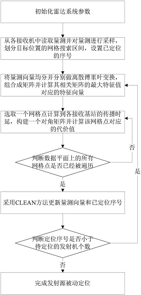
[0050] Such as figure 1 As shown, it is a schematic flowchart of the CLEAN-based passive positioning method for multiple non-cooperative emission sources of the present invention. A CLEAN-based passive location method for multiple non-cooperative emitters, comprising the following steps:

[0051] A. Initialize the radar system parameters, wherein the system parameters include the number of receivers L, the position coordinates of each receiver (x l ,y l ,z l ), l=1,2,...,L, sampling interval T s , the number Q of transmitters to be located;

[0052] B. Read the measurements from each receiver...


PUM


Abstract

The invention discloses a CLEAN based passive positioning method for multiple non-cooperative emission sources. According to the invention, a mesh search method is adopted to directly estimate the position of an emission source from the receiver measurement and then the CLEAN method is applied to delete the information of the emission source from the measurement vectors based on the estimated position of the emission source, followed by the positioning of the next emission source. With the method, it can effectively resolve the problem that a weak emission source with low energy cannot be positioned for the mutual interference among a plurality of emission sources. Therefore, effective positioning of a plurality of emission sources can be achieved. The method can be directly applied to the positioning of a plurality of non-cooperative emission sources of existing passive radar and has great prospects of applications.

Description

technical field [0001] The invention belongs to the technical field of radar signal processing, in particular to a CLEAN-based passive positioning method for multiple non-cooperative emission sources. Background technique [0002] The increasing intensity of electronic warfare has drawn more and more attention to locating multiple non-cooperative emitters in complex environments. In the study of emitter location, the traditional method is mainly based on the two-step location method of angle of arrival (AOA) and time difference of arrival (TDOA). The equation estimates the location of the emission source. However, this method discards a lot of transmitter information in parameter extraction, and the parameter extraction process is usually completed independently in each receiver, so the positioning accuracy is not high. In addition, these traditional positioning methods need to register the extracted parameters first when facing multiple emission sources, which is difficul...

Claims


Application Information

Patent Timeline
IPC IPC(8): G01S13/06
CPCG01S13/06
Inventor 易伟谌振华陈方园李帅孔令讲杨晓波崔国龙
Owner UNIV OF ELECTRONIC SCI & TECH OF CHINA
Why Eureka
Try Eureka