A coil for transient electromagnetic exploration and its application method

A transient electromagnetic and coil technology, applied in the field of transient exploration, can solve the problems of coil sensitivity reduction, complex device form, cumbersome construction, etc., to reduce self-inductance and distributed capacitance, shorten signal transition time, and reduce shallow detection blind zone Effect

Active Publication Date: 2018-06-22
ANHUI HUIZHOU GEOLOGY SECURITY INST
View PDF6 Cites 2 Cited by
  • Summary
  • Abstract
  • Description
  • Claims
  • Application Information

AI Technical Summary

Problems solved by technology

[0003] With the development of geophysical exploration, exploration in complex areas is increasing, and the application of transient electromagnetic method is increasingly limited by the conditions of the working area, especially in urban roads, tunnels, and underground detection. Due to the limited construction environment, only The multi-turn small coil device can be used. After research and application, it is found that the following problems are mainly highlighted: 1) The self-inductance, mutual inductance and distributed capacitance of the coil will increase with the increase of the number of loop turns and the degree of winding density, which in turn will cause the coil The natural frequency decreases and the transient phenomenon is serious (expressed as the emission current is turned off exponentially, the time becomes longer, and the transition time of the induced voltage signal becomes longer), which will seriously affect the effective measurement of early signals, resulting in a large shallow detection blind zone , at the same time, the sensitivity of the coil will also decrease, which will affect the ability to distinguish the target; 2) In the commonly used multi-turn small coils, the transmitting loop and the receiving loop are often independent, and they are not made into a whole. Installing and fixing the two separately is not only cumbersome to use, it is difficult to accurately ensure the consistency of the spatial positions of the two, and it will be difficult to spread the coil in place due to reasons such as the supporting structure and the fixing method, and deformation problems will occur, which will be detrimental to the application effect. influences
The device is to arrange the transmitting and receiving loops in parallel and with a common central axis. The distance between the two is at least 5m. The receiving loop is close to the detection target area, and the transmitting loop is placed behind. Since the transmitting and receiving are far away from each other in this device, it can be large In order to reduce the influence of mutual inductance, there are still many deficiencies, which affect the practical effect, such as: 1) The launch loop is far away from the conductive medium, and the excitation electromagnetic field cannot be well conducted into the surrounding rock medium (deep); 2) The device has a complex form, On-site installation and actual operation require high precision and cumbersome construction

Method used


Image

  • A coil for transient electromagnetic exploration and its application method
  • A coil for transient electromagnetic exploration and its application method
  • A coil for transient electromagnetic exploration and its application method

Examples


Embodiment 1

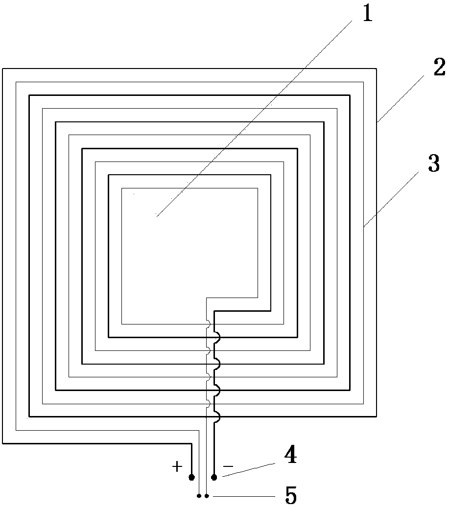
[0036] Such as figure 1 As shown, a coil for transient electromagnetic exploration includes a substrate 1 and a transmitting loop 2 and a receiving loop 3 arranged on the substrate 1, and the transmitting loop 2 and receiving loop 3 are located on the same plane And between the transmitting loop 2, between the receiving loop 3, between the transmitting loop 2 and the receiving loop 3, there is a common center point; between the transmitting loop 2 and the receiving loop 3, keep 1-20cm The spacing is arranged in a rectangular spiral winding manner, and the two are nested with each other turn by turn; the number of turns of the receiving loop 3 is the same as that of the transmitting loop 2, and both are not less than 2 turns; the transmitting The turns of the loop 2 are connected in series to the transmitter through the transmitting terminal 4, and the turns of the receiving coil loop 3 are connected in series to the receiver through the receiving terminal 5. According to the ...

Embodiment 2

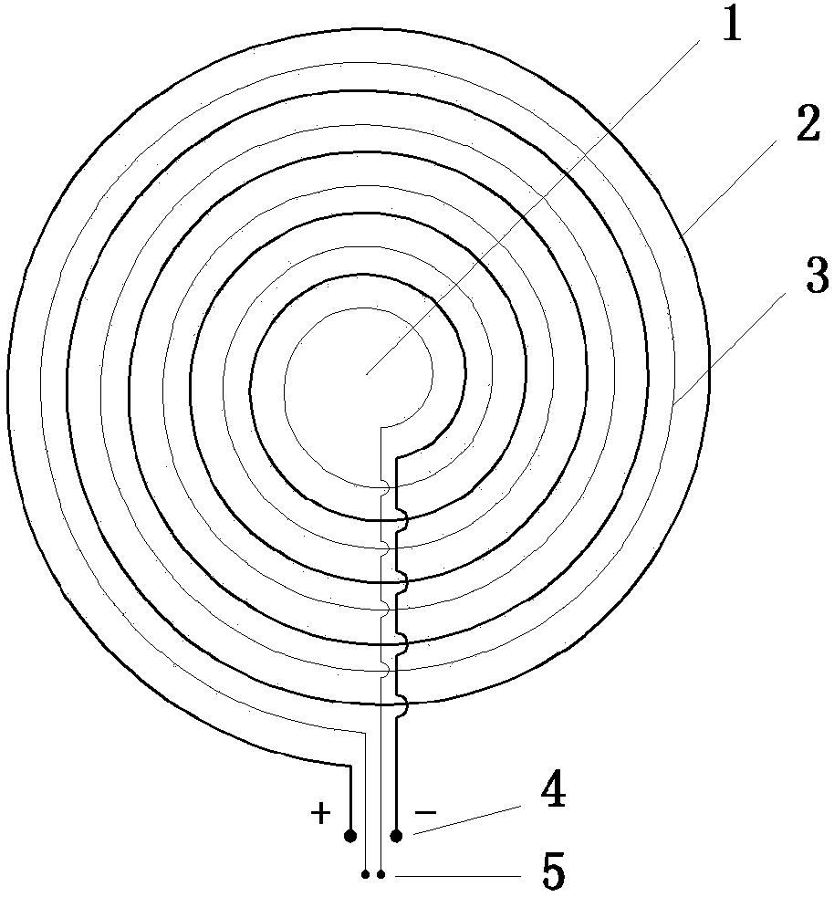
[0037] Embodiment 2: as figure 2 As shown, the transmitting loop 2 and the receiving loop 3 are arranged in a circular spiral winding manner.

Embodiment 3

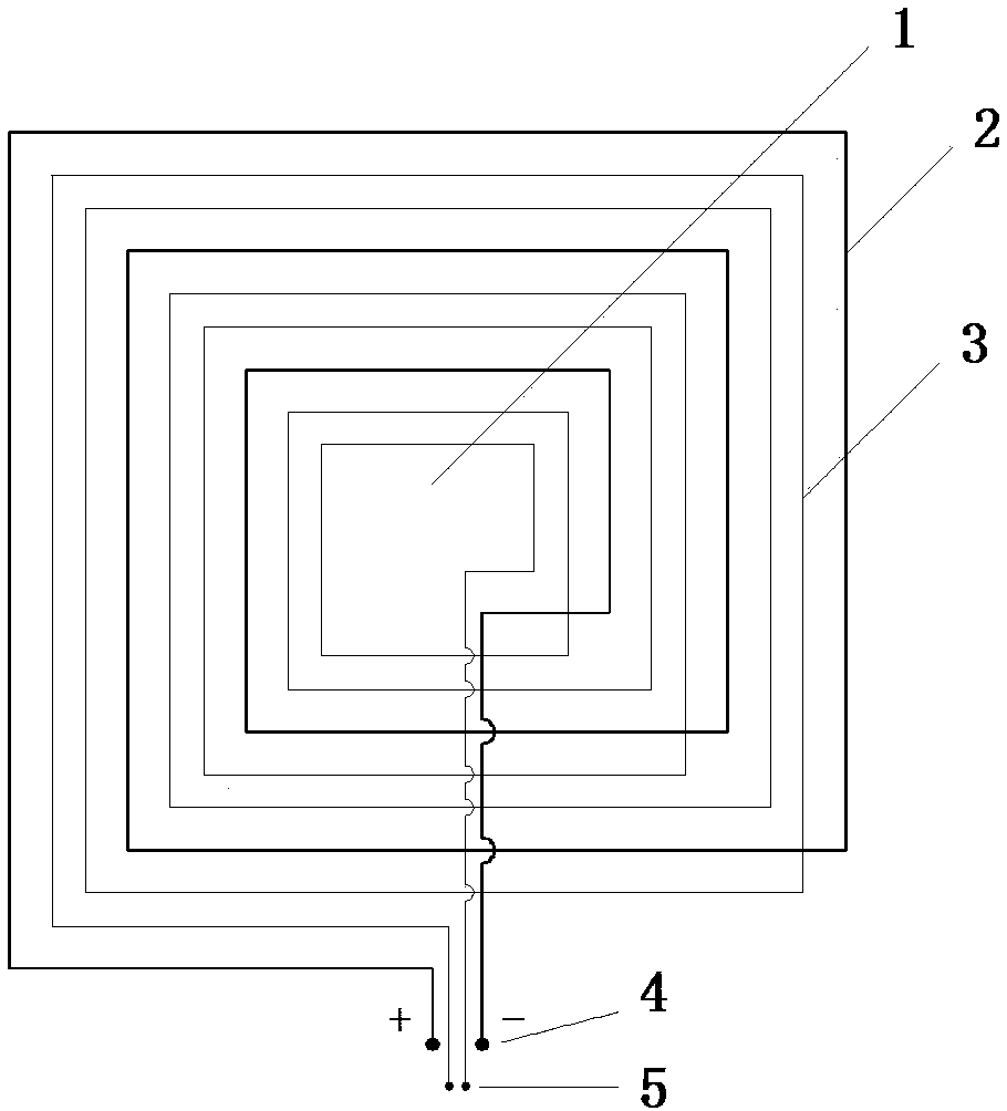
[0038] Embodiment 3: as image 3 As shown, two turns of the receiving loop 3 are embedded between the two adjacent turns of the transmitting loop 2 .


PUM


Abstract

The invention belongs to the technical field of transient electromagnetic explorations and more particularly, to a coil for transient electromagnetic explorations and the application method thereof. The transmitting loops and the receiving loops are arranged on the same plane; among the transmission loops, among the receiving loops and among the transmission loops and the receiving loops, they all share the same central point. The turns of the transmission loops and the turns of the receiving loops are all arranged at some intervals; and the turns are all arranged in a spirally winding manner; and they are mutually embedded and sleeved. The numbers of the turns of the receiving loops are greater or equal to those of the transmitting loops. The turns of the transmitting loops can be either in series connection or in parallel connection; the turns of the receiving loops are in series connection only. The coil of the invention can be independently collected or released. And it is also portable. For the intervals among the receiving loops, under the condition that the number of the turns is a fixed one, it is possible to effectively reduce self-inductance and the distribution capacitance so as to shorten the transient process of the coil. In addition, as the transmitting loops and the receiving loops are mutually embedded and arranged at intervals. The mutual inductance coefficient of the two kinds of loops can be reduced so as to favorably obtain early effective signals, reduce the detection blind area in the shallow part, and improve the exploration in shallow layer, making the coil especially applicable to city engineering geophysical prospecting.

Description

technical field [0001] The invention belongs to the technical field of transient exploration, and in particular relates to a coil for transient electromagnetic exploration and an application method thereof. Background technique [0002] Transient electromagnetic method is a widely used geophysical exploration method, which belongs to time domain electromagnetic method, referred to as TEM. It uses an ungrounded loop to send a pulsed primary magnetic field underground. During the intermittent period of the pulse, the coil is used to observe the distribution information of the secondary electromagnetic field generated by the underground eddy current induced by the pulsed electromagnetic field with space and time. Through extraction and analysis, the Solve related geological problems. [0003] With the development of geophysical exploration, exploration in complex areas is increasing, and the application of transient electromagnetic method is increasingly limited by the conditi...

Claims


Application Information

Patent Timeline
Patent Type & Authority Patents(China)
IPC IPC(8): G01V3/10
CPCG01V3/10
Inventor 刘惠洲周官群曹煜唐润秋吴昭舒玉峰郝志超王宗涛
Owner ANHUI HUIZHOU GEOLOGY SECURITY INST
Why Eureka
Try Eureka